- Excavator steering system anatomy training desk
- Hydraulic front hanging mechanical experimental device
- Water pump performance experimental device
- Contact oxidation pool training desk
- Drinking water treatment process training desk
- Reverse osmosis membrane training
- Softness and salt removal experimental device
- Salvation tank experimental device
- Aerobic biological treatment training device
- Bio -turntable principle experimental device
- Lucky ratio blocking test device
- Socci condiment training desk
- Industrial wastewater treatment training desk
- Industrial wastewater treatment process simulation experimental device
- CNC milling machine installation and maintenance training table
- CNC Machining Center Maintenance and Processing Technical Experimental Desk
- AC Voltage Merragatory System Electrical Experiment Device
- Solar power generation experimental device
- Electrical experimental device of ship anchor machine
- Worker Electrical Engineering Technology Training Device
WeChat:15372285263
Phone:15372285263
WhatsApp:15372285263
Address:Building 3, No. 7 Longyuan Road, Shuige Industrial Park, Liandu District, Lishui City, Zhejiang Province
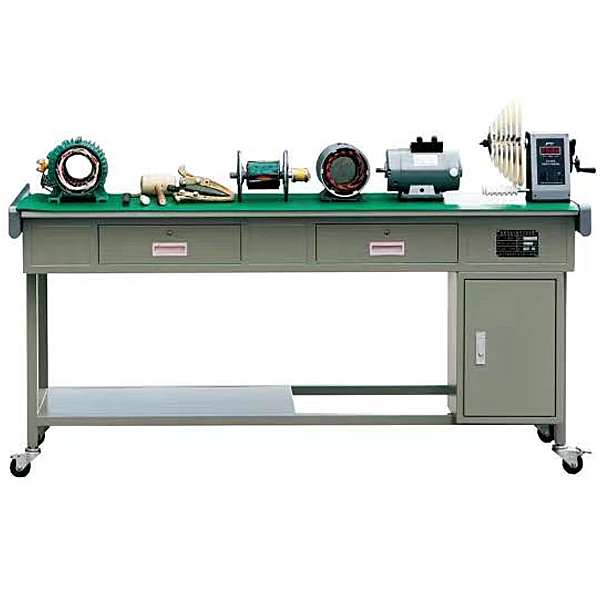
ZOPDJ-CZ motor disassembly experimental device
Motor disassembly experimental desk, synchronous motor disassembly, DC motor disassembly loading through hand -disassembly of commonly used multi -type motors, students can master the composition of the motor from the inside out and the understanding of each component device, according to the characteristics of the motor disassembly.
1. A set of disassembly and assembly tools: 1 puller, 1 adjustable wrench, rubber hammer
1 piece, 1 marking board, 1 crimping board, 1 elbow scissors, 1 needle nose pliers, 1 hacksaw.
2. One 1.1KW three-phase squirrel cage motor.
3. 1 DC separately (parallel) excited motor (100W)
4. 1 steel disassembly and assembly table, specifications: 1500mm×750mm×780mm
5. 1 set of soldering iron and soldering iron stand
Disassembly methods and steps of three-phase asynchronous motor
(a) Cut off the power supply, disassemble the connecting wire between the motor and the power supply, and mark the power supply wire correspondingly to avoid mistaking the phase sequence during recovery, and insulate the ends of the power supply wire.
(b) Prepare all disassembly tools, especially special tools such as pullers and sleeves.
(c) Be familiar with the structural characteristics and disassembly and assembly methods of the disassembled motor.
(d) Measure and record the distance between the coupling or pulley and the pillow block.
(e) Mark the phase sequence of the power cord in the junction box, the outlet direction of the motor and the outlet direction of the lead wire on the machine base.
2. Disassembly steps
As shown in Figure 1, briefly describe the disassembly steps:
(a) Remove the pulley or coupling, and remove the fan cover at the rear of the motor.
(b) Remove the positioning keys or screws and remove the fan.
(c) Unscrew the front and rear end cover fastening screws, and remove the front bearing outer cover.
- Previous:ZOPDLX-03 Change Duty Electric Skills Training Device
- Next:ZOPDG-JS repair electronics technician skills experimental device