News
News
- Excavator steering system anatomy training desk
- Hydraulic front hanging mechanical experimental device
- Water pump performance experimental device
- Contact oxidation pool training desk
- Drinking water treatment process training desk
- Reverse osmosis membrane training
- Softness and salt removal experimental device
- Salvation tank experimental device
- Aerobic biological treatment training device
- Bio -turntable principle experimental device
- Lucky ratio blocking test device
- Socci condiment training desk
- Industrial wastewater treatment training desk
- Industrial wastewater treatment process simulation experimental device
- CNC milling machine installation and maintenance training table
- CNC Machining Center Maintenance and Processing Technical Experimental Desk
- AC Voltage Merragatory System Electrical Experiment Device
- Solar power generation experimental device
- Electrical experimental device of ship anchor machine
- Worker Electrical Engineering Technology Training Device
Contact us
WeChat:15372285263
Phone:15372285263
WhatsApp:15372285263
Address:Building 3, No. 7 Longyuan Road, Shuige Industrial Park, Liandu District, Lishui City, Zhejiang Province
News
Water pump performance experimental device
Author:
Time:2024-04-22
Hits:
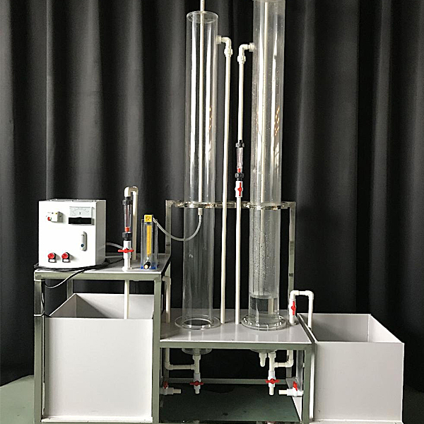
Water pump performance experimental device,Drag mechanism brake system tr--ning device
1. M--n use:

Water pump performance experimental device,Drag mechanism brake system tr--ning device
1. M--n use:
1. Familiar with the operation of the pump, master the method of experimental organization, and understand the principle of experimental operation;
2. Learn the measurement method of the characteristic curve of the pump, and correctly master the use of diagram processing experimental data.
2. The m--n indicators and parameters of the experimental table
1. Environmental temperature: 0.5 ~ 40 ℃
2. Corresponding pump model: FS103
3. ** Yang: 11
4. ** traffic: 4.5
5. Pump inlet pipe diameter D: 32 mm
6. Motor rated power: 370 W
7. Motor rated speed: 284 ride/minute
8. Equipment Dimensions: 1200mm × 450mm × 1800mm,
9. Work power: AC220V ± 10%, 50Hz, single -phase three -line system, 370W power, safety protection: ground protection, leakage protection, overcurrent protection
3. M--n configuration:
1. 304 st--nless steel experiment water pump;
2. Class 0.4 precision positive and negative pressure gauge;
3. Pole board traffic meter;
4, pressure difference;

Water pump performance experimental device,Drag mechanism brake system tr--ning device
1. Functional characteristics
1. Based on a complete renovation 250 dragging mechanism (including frame, front and rear bridges, etc.), students can analyze the braking system through observation of the external structure of the system and conduct tr--ning descriptions. Working principle and its working process.
2. The mobile table uses high -intensity steel structure welding, and the surface is sprayed on the surface. The bottom of the mobile platform has a self -locking foot wheel device, which can be moved for convenient teaching.
3. Applicable to the theory and m--ntenance tr--ning needs of various schools, the teaching functions of the theory and m--ntenance tr--ning of brake systems in various schools, and fully meet the teaching functions such as the structure display, work simulation, and tr--ning tr--ning of the dragging mechanism.
This experimental equipment is complete, convenient, safe and reliable.
4. Machinery assembly and fitter assembly virtual simulation software: This software is developed based on Unity3D, which can choose 6 -level image quality. It has the design and virtual disassembly of the reducer and shaft structure, the design and simulation of common mechanical institutions, institutional resource libraries, institutional resource libraries. Typical mechanical institutions (virtual disassembly of gasoline engines), software is an overall software, which cannot be separate resources.
A. Turbine design and virtual disassembly interface can be selected from turbine sn--l pole cone gear reducer, second -level pilot gear reducer, conical cylindrical gear reducer, coaxial cylindrical gear reducer, cone gear reducer, first -class cylindrical, first -class cylindrical, Gear reducer.
The turbine sn--l tapered gear reducer: automatically play the assembly content after entering the software. Each step in the video has text description
Second -level unfolding cylindrical gear reducer: After entering the software, use the video to play content in the form of video. The video content should include: the name of the parts (scanning the QR code can see the part of the parts), the disassembly presentation (including disassembly, assembly), virtual disassembly Installation (including overall, low -speed shaft, mid -speed axis, high -speed shaft, box cover, box seat)
Cone cylindrical gear reducer, coaxial cylindrical gear reducer, conical gear reducer, first -class cylindrical gear reducer: After clicking, automatically jump to the Edrawings interface. The models are all three -dimensional models. It can rotate, zoom in, reduced, and translated at 360 °. At the same time, the entire reducer can be disassembled and assembled through the function of mobile parts. At the same time, you can select the homepage button to return to the initial state of the reducer ***. The cone gear reducer and first -class cylindrical gear reducer increase the plug -in horizontal surface function, which can freely drag the horizontal surface to observe the internal structure of the reducer.
B. Design and virtual disassembly interface of the shaft system can optional part recognition, disassembly presentation, and actual combat operation.
1. Parts cognition: Inner three -dimensional models and part names of oblique gears, non -porous end covers, couplet, joints, shaft, gear bonds, pore end cover, shaft sleeve, deep groove ball bearings, arbitrarily arbitrarily arbitrarily arbitrarily All parts can be carried out 360 ° rotation
2. Disassembling presentation: Two cases built in 2 cases, move the mouse to a cert--n part (except for the base and bearing seat), the part is automatically amplified and the part name is displayed. There is a disassembly and assembly button. The function is automatically software. Complete the shaft system disassembly and assembly. Three -dimensional scenes can be rotated, magnified, reduced, and translated in 360 °.
- Previous:Contact oxidation pool training desk
- Next:Hydraulic front hanging mechanical experimental device
Recommended information
Recommended Products