- Excavator steering system anatomy training desk
- Hydraulic front hanging mechanical experimental device
- Water pump performance experimental device
- Contact oxidation pool training desk
- Drinking water treatment process training desk
- Reverse osmosis membrane training
- Softness and salt removal experimental device
- Salvation tank experimental device
- Aerobic biological treatment training device
- Bio -turntable principle experimental device
- Lucky ratio blocking test device
- Socci condiment training desk
- Industrial wastewater treatment training desk
- Industrial wastewater treatment process simulation experimental device
- CNC milling machine installation and maintenance training table
- CNC Machining Center Maintenance and Processing Technical Experimental Desk
- AC Voltage Merragatory System Electrical Experiment Device
- Solar power generation experimental device
- Electrical experimental device of ship anchor machine
- Worker Electrical Engineering Technology Training Device
WeChat:15372285263
Phone:15372285263
WhatsApp:15372285263
Address:Building 3, No. 7 Longyuan Road, Shuige Industrial Park, Liandu District, Lishui City, Zhejiang Province
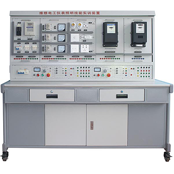
ZOPWXG-01D Maintenance Electric Instrument Lighting Skills Experimental Device
Maintenance Electric Instrument Lighting Skills Experimental desk, the instrument lighting experimental device is designed as a dual -group type. The power supply on the left and right sides of the control screen is independent and does not interfere with each other. It can be used to complete the training operation with two students. Electrical control line components are installed on the installation board as a hanging board.
1. Device features:
1. The electrical control circuit components are all installed on the mounting plate as a hanging plate, which is easy to operate and replace, making it easy to expand functions or develop new tr*ning. The selection of operation content is typical and practical;
2. The operating console only needs three-phase four-wire AC power supply to be put into use;
3. The device is equipped with voltage and current leakage protectors to ensure the personal safety of the operator;
4. All components are led to the terminal blocks through wires. Students only need to perform wiring on the terminals, which is helpful to protect the components;
5. Route wires through wire troughs and conduct process wiring tr*ning. The connection between the tr*ning circuit and the device power supply is through a safety socket and a high-reliability sheathed pistol plug cord, which is safe and fast.
6. The device is designed as a double-group type. The left and right sides of the control panel have independent power supplies and do not interfere with each other, allowing two students to complete practical tr*ning operations at the same time.
7. Electrical safety and electric shock first *d simulation teaching software
The software uses a combination of two-dimensional and three-dimensional virtual images to teach students the safety and first *d methods of using electricity. The software includes single-phase electric shock, two-phase electric shock, step electric shock, low-voltage electric shock first *d, high-voltage electric shock first *d, artificial respiration first *d, Principles of hand-holding breathing rescue method, chest cardiac compression and other protective methods are expl*ned and taught. Principles of single-phase electric shock are divided into rep*ring live disconnection, rep*ring socket electric shock, and outdoor electric shock. The teaching of low-voltage electric shock and high-voltage electric shock m*nly expl*ns and demonstrates to students how to rescue people who are suffering from low-voltage electric shock or high-voltage electric shock. Artificial respiration rescue method, hand-holding breathing rescue method, and chest cardiac compression rescue method are demonstrated using 3D virtual simulation technology. After rendering and Polish it to make the model look like the real part and look realistic. Through practical tr*ning, students can be educated on the safe use of electricity in the tr*ning room, improve students' safety awareness, and enable students to learn some self-rescue methods, so that students can take cert*n safety measures to protect themselves when encountering danger, and become familiar with various Causes of electrical accidents and practical measures to deal with them to reduce the occurrence of electrical accidents.
8. M*ntenance of electricians, electronic motors and vocational qualification tr*ning assessment simulation software
This software is in apk format and can be used on PC or mobile. This software can set faults manually or automatically. This software can manually set fault points through the green box in the circuit diagram (you can set up to 39 fault points), you can also automatically set one random fault point, two random fault points, three random fault points, four random fault points, and five random fault points through the system. It has functions such as toolbox, component library, magnifying glass, circuit diagram, etc. You can choose a multimeter for testing through the toolbox, select appropriate components through the component library, and clearly understand each component and circuit through the magnifying glass. This software allows students to understand the working principle and circuit structure of the motor star-delta start control circuit through the setting of faults in the motor star-delta start control circuit and various investigations.
9. Virtual spectrum analyzer, logic analyzer, oscilloscope, and three-meter simulation software:
This software is in apk format and can be used on PC or mobile terminals. The functions of this software are: resistance measurement, AC voltage measurement (measuring transformer, if the multimeter burns out when measuring the transformer, black smoke will emit prompts and can reset the multimeter), determine the polarity of the transistor, measure the DC voltage (the light turns on when the ammeter is turned on), measure the DC current, and determine the quality of the capacitor. This software can drag the red and black pen tips at will. When the two pen tips are dragged and positioned on the object to be measured, a red circle will be displayed. If the positioning is not accurate, no red circle will be displayed, and when incorrect operations are performed (such as the wrong range selected, If the measured data is wrong, etc.), the meter pointer will be unresponsive, prompting errors and re-measurement, etc. This multimeter can select AC voltage range, DC voltage range, resistance range, current range, resistance adjustment to 0, and can enlarge the display data. Clearly view the measured data size. Students can learn the correct use of multimeters through this software.
10. Microcontroller and plc programmable design and control virtual simulation software:
This software is developed based on unity3d and has built-in experimental steps, experimental instructions, circuit diagrams, component lists, connection lines, power on, circuit diagrams, scene reset, return and other buttons. After the connections and codes are correct, you can start/stop, The forward movement and reverse movement buttons operate the 3D machine tool model to move. In the connected line state, the 3D machine tool model can be enlarged/reduced and translated.
1. Relay control: Read the experiment instructions and enter the experiment. By reading the circuit diagram, select the relays, thermal relays, switches and other components in the component list and drag and drop them into the electrical cabinet. The limiters are placed in the three-dimensional On the machine tool model, you can choose to cover it, and some component names can be renamed. Then click the Connect Line button to connect terminals to terminals. After successfully connecting the machine tool circuit, choose to turn on the power and proceed. If the component or line An error box will pop up if there is a connection error, and the scene can be reset at any time.
2. PLC control: The experiment is the same as relay control, with the addition of PLC control function. After the connection is completed, enter the program writing interface through the PLC coding button, and write two programs, forward and reverse, with a total of 12 ladder diagram symbols. The writing is completed. Finally, select Submit for program verification. After the verification is successful, turn on the power for operation. Error boxes will pop up for component, line connection, and code errors, and the scene can be reset at any time.
3. Single-chip microcomputer control: The experiment is the same as relay control, with the addition of single-chip microcomputer control function. After the connection is completed, enter the programming interface through the C coding button, enter the correct C language code, and after successful submission and verification, turn on the power for operation, components, lines If there are connection or code errors, an error box will pop up, and the scene can be reset at any time.
2. Technical performance:
1. Input voltage: three-phase four-wire (or three-phase five-wire) ~ 380V±10% 50Hz
2. Working environment: temperature -10~+40℃, relative humidity <85% (25℃), altitude <4000m
3. Device capacity: <1.5KVA
4. Weight: 100Kg
5. Overall dimensions: 1605×805×1630mm3
6. Leakage protection action current: ≤30mA; leakage protection action time: ≤0.1s.
3. Basic configuration and functions of the device
The tr*ning platform is equipped with two sets of power supplies. The output of the power supply is controlled through start and stop buttons, and is equipped with an emergency stop button. The power output is equipped with short circuit protection.
1. AC power supply: The tr*ning platform provides two power supplies with line voltage 380V and phase voltage 220V, and is also equipped with multiple single-phase and three-phase power sockets;
2. Rectifier diodes: Four rectifier diodes 1N5408 are provided for energy consumption braking circuit.
3. Resistors of various specifications
Three 75Ω/75W power resistors are provided for step-down starting circuit.
A 10Ω/25W power resistor is provided for energy consumption braking circuit.
4. Intelligent multi-functional AC circuit measuring ammeter: eight-digit LED display, which can simultaneously measure the current I, voltage V, power KW, electric energy KWh, and working time T in the working circuit, with an accuracy of 1.0 level.
5. Tr*ning table: The tr*ning table is made of iron with a double-layer matte dense spray-p*nted structure. The tabletop is made of fireproof, waterproof, wear-resistant high-density board, with a solid structure and beautiful appearance. There are two drawers on the left and right sides of the table.
4. Practical tr*ning projects
1. A socket and a switch control a lamp (incandescent lamp, fluorescent lamp + two-pole leakage switch)
2. Two double switches control one lamp (incandescent lamp, fluorescent lamp + two-pole leakage switch)
3. Three switches control one lamp (incandescent lamp, fluorescent lamp + two-pole leakage switch)
4. Wiring of fluorescent lamp circuit
5. Voice-activated switch controls the wiring of incandescent lamp circuit
6. Touch delay switch to control the wiring of incandescent lamp circuit
7. Human body sensor switch controls the wiring of incandescent lamp circuit
8. Single-phase watt-hour meter direct wiring circuit
9. Wiring circuit of single-phase electricity meter through current transformer
10. Voltmeter and ammeter wiring circuit
11. Universal transfer switch voltmeter measures three-phase voltage wiring
12. A current transformer is used for the control circuit wiring of a single-phase circuit.
13.Three current transformers are connected into a star wiring circuit
14. Three current transformers are connected to form a delta wiring circuit
15.Measurement circuit of three-phase power factor meter
16. Wiring circuit of three-phase three-wire active energy meter
17. Connection circuit of three-phase three-wire active electricity meter through current transformer
18. Wiring circuit of three-phase four-wire active energy meter
19. Connection circuit of three-phase four-wire reactive power meter through current transformer
20. Wiring circuit of three-phase four-wire reactive power meter
21. Connection circuit of three-phase four-wire reactive power meter through current transformer
5. Configuration of practical tr*ning components
|
serial number |
Hanging box number |
Practical tr*ning module name |
quantity |
Remark |
|
1 |
DW-10 |
Instrument lighting tr*ning and assessment components (1) |
1 item |
Provides 1 diode leakage protector, 2 3P fuses, 1 switch, and 1 single-phase electricity meter. |
|
2 |
DW-11 |
Instrument lighting practical tr*ning and assessment components (2) |
1 item |
Provide 2 screw lamp holders, 3 switch boxes, 1 ballast, 1 starter, 1 fluorescent lamp, 2 toggle switches, and 1 double switch |
|
3 |
DW-12 |
Instrument lighting tr*ning and assessment components (3) |
1 item |
Provide 3 AC ammeters and 3 current transformers |
|
4 |
DW-13 |
Instrument lighting tr*ning and assessment components (4) |
1 item |
Provide 1 AC voltmeter and 1 voltage indication switch |
|
5 |
DW-14 |
Instrument lighting tr*ning and assessment components (5) |
1 item |
Provide 1 three-phase three-wire active energy meter |
|
6 |
DW-15 |
Instrument lighting tr*ning and assessment components (6) |
1 item |
Provide 1 three-phase four-wire active energy meter |
|
7 |
DW-16 |
Instrument lighting tr*ning and assessment components (7) |
1 item |
Provide 1 three-phase four-wire reactive energy meter |
- Previous:ZOPWXG-02A Maintenance Electric Training Device
- Next:ZOPWXG-01A Primary Maintenance Electrician Training Device