- Excavator steering system anatomy training desk
- Hydraulic front hanging mechanical experimental device
- Water pump performance experimental device
- Contact oxidation pool training desk
- Drinking water treatment process training desk
- Reverse osmosis membrane training
- Softness and salt removal experimental device
- Salvation tank experimental device
- Aerobic biological treatment training device
- Bio -turntable principle experimental device
- Lucky ratio blocking test device
- Socci condiment training desk
- Industrial wastewater treatment training desk
- Industrial wastewater treatment process simulation experimental device
- CNC milling machine installation and maintenance training table
- CNC Machining Center Maintenance and Processing Technical Experimental Desk
- AC Voltage Merragatory System Electrical Experiment Device
- Solar power generation experimental device
- Electrical experimental device of ship anchor machine
- Worker Electrical Engineering Technology Training Device
WeChat:15372285263
Phone:15372285263
WhatsApp:15372285263
Address:Building 3, No. 7 Longyuan Road, Shuige Industrial Park, Liandu District, Lishui City, Zhejiang Province
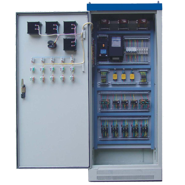
ZOPWXG-02A Maintenance Electric Training Device
Maintenance electrical training cabinet (double -sided), primary maintenance electrical training device cabinets are equipped with electrical meters, fluorescent lamps, switches, sockets, induction switches, leakage switches, and electrical control required for the circuit.
Technical parameters:
Input power supply: AC380V±5% (three-phase five-wire) 50Hz Rated current: 15A
Ambient temperature: -5℃~40℃
Dimensions: 700×450×1700mm Equipment weight: 100kg
Product composition:
1. Practical tr*ning Cabinet
The tr*ning cabinet is made of iron matte dense spray-p*nted structure: it is extruded from cold-rolled steel plates. The tr*ning cabinet cont*ns four universal moving wheels with foot brakes.
2. The cabinet door
(1) is equipped with an AC voltmeter, an AC ammeter, and a voltage indication switch; the power supply emergency stop button and start-stop switch of the control cabinet are controlled. The voltage indication switch can indicate the UUV and UVW of the power grid respectively. , UWU line voltage value; equipped with AC ammeter to monitor the load size.
(2) Safety protection system.
1) The three-phase power supply of the power grid passes through the leakage protector, AC contactor, and then is output to each tr*ning power through the circuit breaker.
2) It is equipped with a leakage protection device with an operating current of 30mA, which can automatically cut off the m*n power supply in case of leakage during tr*ning.
3) It is equipped with an over-current protection device. If the output is short-circuited or the load is too large and the current exceeds the set value, the system will cut off the m*n power supply.
4) Power f*lure protection.
5) The device adopts grounding protection.
6) Teaching software
1. Electrical safety and electric shock first *d simulation teaching software
The software uses a combination of two-dimensional and three-dimensional virtual images to teach students the safety and first *d methods of using electricity. The software includes single-phase electric shock, two-phase electric shock, step electric shock, low-voltage electric shock first *d, high-voltage electric shock first *d, artificial respiration first *d, Principles of hand-holding breathing rescue method, chest cardiac compression and other protective methods are expl*ned and taught. Principles of single-phase electric shock are divided into rep*ring live disconnection, rep*ring socket electric shock, and outdoor electric shock. The teaching of low-voltage electric shock and high-voltage electric shock m*nly expl*ns and demonstrates to students how to rescue people who are suffering from low-voltage electric shock or high-voltage electric shock. Artificial respiration rescue method, hand-holding breathing rescue method, and chest cardiac compression rescue method are demonstrated using 3D virtual simulation technology. After rendering and Polish it to make the model look like the real part and look realistic. Through practical tr*ning, students can be educated on the safe use of electricity in the tr*ning room, improve students' safety awareness, and enable students to learn some self-rescue methods, so that students can take cert*n safety measures to protect themselves when encountering danger, and become familiar with various Causes of electrical accidents and practical measures to deal with them to reduce the occurrence of electrical accidents.
2. M*ntenance of electricians, electronic motors and vocational qualification tr*ning assessment simulation software
This software is in apk format and can be used on PC or mobile. This software can set faults manually or automatically. This software can manually set fault points through the green box in the circuit diagram (you can set up to 39 fault points), you can also automatically set one random fault point, two random fault points, three random fault points, four random fault points, and five random fault points through the system. It has functions such as toolbox, component library, magnifying glass, circuit diagram, etc. You can choose a multimeter for testing through the toolbox, select appropriate components through the component library, and clearly understand each component and circuit through the magnifying glass. This software allows students to understand the working principle and circuit structure of the motor star-delta start control circuit through the setting of faults in the motor star-delta start control circuit and various investigations.
3. Virtual spectrum analyzer, logic analyzer, oscilloscope, and three-meter simulation software:
This software is in apk format and can be used on PC or mobile terminals. The functions of this software are: resistance measurement, AC voltage measurement (measuring transformer, if the multimeter burns out when measuring the transformer, black smoke will emit prompts and can reset the multimeter), determine the polarity of the transistor, measure the DC voltage (the light turns on when the ammeter is turned on), measure the DC current, and determine the quality of the capacitor. This software can drag the red and black pen tips at will. When the two pen tips are dragged and positioned on the object to be measured, a red circle will be displayed. If the positioning is not accurate, no red circle will be displayed, and when incorrect operations are performed (such as the wrong range selected, If the measured data is wrong, etc.), the meter pointer will be unresponsive, prompting errors and re-measurement, etc. This multimeter can select AC voltage range, DC voltage range, resistance range, current range, resistance adjustment to 0, and can enlarge the display data. Clearly view the measured data size. Students can learn the correct use of multimeters through this software.
4. Microcontroller and plc programmable design and control virtual simulation software:
This software is developed based on unity3d and has built-in experimental steps, experimental instructions, circuit diagrams, component lists, connection lines, power on, circuit diagrams, scene reset, return and other buttons. After the connections and codes are correct, you can start/stop, The forward movement and reverse movement buttons operate the 3D machine tool model to move. In the connected line state, the 3D machine tool model can be enlarged/reduced and translated.
1. Relay control: Read the experiment instructions and enter the experiment. By reading the circuit diagram, select the relays, thermal relays, switches and other components in the component list and drag and drop them into the electrical cabinet. The limiters are placed in the three-dimensional On the machine tool model, you can choose to cover it, and some component names can be renamed. Then click the Connect Line button to connect terminals to terminals. After successfully connecting the machine tool circuit, choose to turn on the power and proceed. If the component or line An error box will pop up if there is a connection error, and the scene can be reset at any time.
2. PLC control: The experiment is the same as relay control, with the addition of PLC control function. After the connection is completed, enter the program writing interface through the PLC coding button, and write two programs, forward and reverse, with a total of 12 ladder diagram symbols. The writing is completed. Finally, select Submit for program verification. After the verification is successful, turn on the power for operation. Error boxes will pop up for component, line connection, and code errors, and the scene can be reset at any time.
3. Single-chip microcomputer control: The experiment is the same as relay control, with the addition of single-chip microcomputer control function. After the connection is completed, enter the programming interface through the C coding button, enter the correct C language code, and after successful submission and verification, turn on the power for operation, components, lines If there are connection or code errors, an error box will pop up, and the scene can be reset at any time.
3. Internal configuration module:The internal space is divided into different areas with wiring troughs, and the layout is reasonable. All electrical component terminals have been led to the dedicated terminal strip. Students can connect/wiring from the terminal strip to get close to the industrial site.
(1) AC power supply
: There is a set of control transformers. The primary side accepts 380V AC power input, and the secondary side of the transformer can output AC voltages of 110V, 36V, 24V, 12V, and 6.3V.
(2) Instrumentation:
AC voltmeter is provided with a measuring range of 0~500V and an accuracy of level 2.5.
Provide AC ammeter with measuring range of 0~5A and accuracy of level 2.5.
4. Mesh plate:
The mesh plate is made of high-quality cold-rolled steel plate, with a double-surface matte dense texture spray-p*nted structure, which is strong and durable.
5. Components det*led list
| serial number | item name | Specifications and models | quantity | unit |
| 1 | pointer ammeter | 62L6-A 5A | 3 | |
| 2 | pointer voltmeter | 62L6-V 450V | 1 | |
| 3 | Current Transformer | LMZJ1-0.5 30/5A | 3 | |
| 4 | Leakage circuit breakers | DZ15LE-40/490 | 1 | |
| 5 | Active energy meter | DT862-2 | 1 | |
| 6 | breaker | DZ47LE-63 C16 3P | 2 | |
| 7 | Time Relay | JS7-4A 110V | 2 | |
| 8 | Intermediate relay | ZJ7-44 110V | 2 | |
| 9 | AC contactor | CJT-10 110V | 5 | |
| 10 | thermal relay | JR36-20 3.6A | 3 | |
| 11 | Limit switch | LX19-121 | 3 | |
| 12 | Universal transfer switch | LW5D-16YH3/3 | 1 | |
| 13 | fuse holder | RT14-20 | 7 | |
| 14 | fuse | 3A | 7 | |
| 15 | indicator light | PBCY090 220V red | ||
| 16 | power switch button | PBCY090 red | 5 | |
| 17 | power switch button | PBCY090 green | 5 | |
| 18 | Terminals | TD1530 | 4 | |
| 19 | Terminals | TD1562 | 2 | |
| 20 | Cold press plug | Φ3 .Φ4 | several | |
| twenty one | nameplate | Φ22 | 15 | |
| twenty two | bobbin | Φ8 | several | |
| twenty three | suction cup | several | ||
| twenty four | Crimping trough | 3030 | several | |
| 25 | Three-phase asynchronous motor | 380V 180W | 2 units | |
| 26 | Experiment instructions | 1 set | ||
| 27 | Other supporting equipment | 1 set | ||
Practical tr*ning content
1. Knife switch forward control circuit
2. Contact point dynamic forward control circuit
3. Forward control circuit with self-locking
4. Forward control circuit with overload protection
5. Reverse switch controls forward and reverse rotation Control circuit
6, contactor interlocking forward and reverse control circuit
7, button interlocking forward and reverse control circuit
8, button contactor composite interlocking control circuit
9, automatic round trip control circuit
10, contactor control series resistance drop Voltage starting circuit
11, time relay control series resistor voltage reduction control circuit
12, manual Y/△ voltage reduction start
13, contactor control Y/△ voltage reduction start
14, time relay control Y/△ voltage reduction start
15, QX3-13 Type Y/△ automatic starting control circuit
16, half-wave rectification energy consumption braking control circuit
17, full-wave rectification energy consumption braking control circuit
18, C620 lathe electrical control circuit
19, manual step-down starting
20, single-phase operation reverse connection Brake control circuit
21, electric hoist electrical control circuit
22, current transformer and ammeter matching wiring circuit
23, one current transformer for single-phase circuit wiring circuit
24, two current transformers connected into an unsafe star connection Circuit
25. Three current transformers connected to form a star connection circuit
26. Two current transformers connected to a differential connection circuit
27. Three current transformers connected to a delta connection circuit
28. Universal transfer switch and voltmeter to measure three-phase voltage connection circuit
- Previous:ZOPDJB-01 motor, transformer maintenance and detection experimental device
- Next:ZOPWXG-01D Maintenance Electric Instrument Lighting Skills Experimental Device