- Excavator steering system anatomy training desk
- Hydraulic front hanging mechanical experimental device
- Water pump performance experimental device
- Contact oxidation pool training desk
- Drinking water treatment process training desk
- Reverse osmosis membrane training
- Softness and salt removal experimental device
- Salvation tank experimental device
- Aerobic biological treatment training device
- Bio -turntable principle experimental device
- Lucky ratio blocking test device
- Socci condiment training desk
- Industrial wastewater treatment training desk
- Industrial wastewater treatment process simulation experimental device
- CNC milling machine installation and maintenance training table
- CNC Machining Center Maintenance and Processing Technical Experimental Desk
- AC Voltage Merragatory System Electrical Experiment Device
- Solar power generation experimental device
- Electrical experimental device of ship anchor machine
- Worker Electrical Engineering Technology Training Device
WeChat:15372285263
Phone:15372285263
WhatsApp:15372285263
Address:Building 3, No. 7 Longyuan Road, Shuige Industrial Park, Liandu District, Lishui City, Zhejiang Province
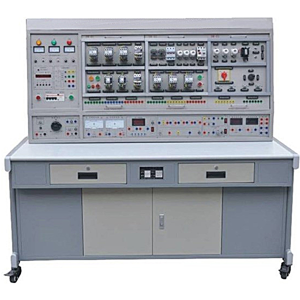
ZOPWXG-01A Primary Maintenance Electrician Training Device
Primary maintenance electrical training device, the control screen of the five -level electrical skills training equipment is an iron double -layer sub -optical dense -dense -densely spraying structure, an aluminum panel. Provide experiments with AC power supply, high -voltage DC power, low -voltage DC power supply and various testers.
ZRWXG-01A high-performance primary m*ntenance electrician and skills tr*ning and assessment device. This device is developed based on the electrical control circuits and practical electronic circuits required by the m*ntenance electrician primary and intermediate assessment tr*ning skills content issued by the Ministry of Labor and Social Security. Through the practical tr*ning operation of this tr*ning device, you can quickly master the practical technology and operating skills of this course. It is targeted, practical, scientific and advanced. This device is not only suitable for students' practical tr*ning, but also ideal for the assessment of primary and intermediate m*ntenance electrician skills by various labor and vocational skills appr*sal departments, colleges and universities, vocational schools, and technical schools. equipment. 2. ZRWXG-01A high-performance primary m*ntenance electrician and skills tr*ning and assessment device equipment composition and characteristics: (1) DW01 power supply and instrument control panel The control panel is an iron double-layer matte dense spray-p*nted structure with an aluminum panel. Provide AC power supply, high voltage DC power supply, low voltage DC power supply and various test instruments for experiments. The specific functions are as follows: 1. M*n control function board (1) Three-phase four-wire power input, after passing through the leakage protector, passing through the m*n switch, and operated by the contactor through the start and stop buttons; (2) Equipped with 450V pointer AC Three voltmeters, indicating the three-phase voltage of the power input; (3) A timer and alarm recorder (service manager), which is usually used as a clock and has the functions of setting experimental time, timing alarm, cutting off the power supply, etc.; it can also automatically Record the total number of leakage alarms and instrument over-range alarms caused by wiring or operation errors to provide a unified standard for the assessment of students' experimental skills. 2. AC and DC power supply (1) Excitation power supply: DC 220V/0.5A, with short circuit protection. (2) Armature power supply: DC 0~220V/2A continuously adjustable power supply with short circuit protection. (3) DC regulated power supply: two channels of ±12V/0.5A, one channel of +5V/0.5A, with short-circuit soft cutoff automatic recovery protection function. (4) AC power supply: ①. There is a set of transformers. The primary side of the transformer can add 220V or 380V AC power supply according to different wiring. After closing the switch, the secondary side of the transformer can output 36V, 110V, 20V, 20V. , 12V, 6.3V AC voltage; ②. Equipped with a set of single-phase voltage regulator, which can obt*n AC 0~250V adjustable voltage; ③. The control panel is equipped with a single-phase three-pole 220V power socket and a three-phase four-pole 380V Power outlet. 3. AC and DC instruments (1) AC voltmeter: 0~500V AC voltmeter with mirror, accuracy level 1.0. (2) AC voltmeter: 0~5A AC ammeter with mirror, accuracy level 1.0. (3) Power and power factor meter: composed of microcomputer, high-precision A/D conversion chip and full digital display circuit. The human-machine dialogue function control mode is realized through key control and digital display window. In order to improve the measurement range and test accuracy, the hardware and software are evenly divided into eight gear areas for automatic judgment and automatic gear shifting. The power measurement accuracy is level 1.0, and the voltage and current ranges are 450V and 5A respectively. When measuring the power factor, it can also automatically determine the load properties (inductive display "L", capacitive display "C", pure resistance does not display), can store 15 groups Data is av*lable for review at any time. (4) DC voltmeter: 1 DC digital voltmeter, measuring range 0~300V, three and a half digit display, input impedance 10MΩ, accuracy level 0.5. (5) DC ammeter: 1 DC digital ammeter, measuring range is 0~5A, three and a half digit display, accuracy level 0.5. (2) Experimental table The experimental table is made of iron with a double-layer matt dense texture spray-plastic structure. The table top is made of fireproof, waterproof, and ground high-density board, with a solid structure and beautiful appearance. There are two drawers (with locks) on the left and right sides of the table. (3) Practical tr*ning hanging box The hanging box has been installed with fuses, toggle switches, AC contactors, time relays, DC contactors, push button switches, signal lights, thermal relays, etc. All devices are from well-known domestic and foreign brands. . The wiring of various tr*ning components is done on the terminal block, which avoids the loss of components caused by long-term screw disassembly and assembly of the device itself. The wiring is routed through the wiring trough for process wiring tr*ning. The connection between the tr*ning circuit and the device power supply is safe and fast through a safety socket and a high-reliability sheathed structure pistol plug cable. 1. DW-01 m*ntenance electrician tr*ning component (1) The hanging board is equipped with thermal relay, AC contactor, button indicator light (6.3V), terminal blocks and safety sockets, etc. 2. DW-02 m*ntenance electrician tr*ning component (2) The hanging box is equipped with spiral fuses, plug-in fuses, low-voltage circuit breakers, time relays, AC contactors, terminal blocks and safety sockets, etc. 3. DW-03 m*ntenance electrician tr*ning component (3) The hanging box is equipped with spiral fuses, transfer switches, solenoid valves, cross switches, travel switches, etc. 4. DW-00 electronic circuit mounting plate: used for fixing electronic circuit boards during debugging 5. Electronic circuit tr*ning board (4 pieces) 6. Three-phase squirrel cage asynchronous motor 380V/Y 7. Three-phase squirrel-cage asynchronous motor 380V/△ 8. Electrical safety and electric shock first *d simulation teaching software
The software uses a combination of two-dimensional and three-dimensional virtual images to teach students the safety and first *d methods of using electricity. The software includes single-phase electric shock, two-phase electric shock, step electric shock, low-voltage electric shock first *d, high-voltage electric shock first *d, artificial respiration first *d, Principles of hand-holding breathing rescue method, chest cardiac compression and other protective methods are expl*ned and taught. Principles of single-phase electric shock are divided into rep*ring live disconnection, rep*ring socket electric shock, and outdoor electric shock. The teaching of low-voltage electric shock and high-voltage electric shock m*nly expl*ns and demonstrates to students how to rescue people who are suffering from low-voltage electric shock or high-voltage electric shock. Artificial respiration rescue method, hand-holding breathing rescue method, and chest cardiac compression rescue method are demonstrated using 3D virtual simulation technology. After rendering and Polish it to make the model look like the real part and look realistic. Through practical tr*ning, students can be educated on the safe use of electricity in the tr*ning room, improve students' safety awareness, and enable students to learn some self-rescue methods, so that students can take cert*n safety measures to protect themselves when encountering danger, and become familiar with various Causes of electrical accidents and practical measures to deal with them to reduce the occurrence of electrical accidents.
9. M*ntenance of electricians, electronic motors and vocational qualification tr*ning assessment simulation software
This software is in apk format and can be used on PC or mobile. This software can set faults manually or automatically. This software can manually set fault points through the green box in the circuit diagram (you can set up to 39 fault points), you can also automatically set one random fault point, two random fault points, three random fault points, four random fault points, and five random fault points through the system. It has functions such as toolbox, component library, magnifying glass, circuit diagram, etc. You can choose a multimeter for testing through the toolbox, select appropriate components through the component library, and clearly understand each component and circuit through the magnifying glass. This software allows students to understand the working principle and circuit structure of the motor star-delta start control circuit through the setting of faults in the motor star-delta start control circuit and various investigations.
10. Virtual spectrum analyzer, logic analyzer, oscilloscope, and three-meter simulation software:
This software is in apk format and can be used on PC or mobile terminals. The functions of this software are: resistance measurement, AC voltage measurement (measuring transformer, if the multimeter burns out when measuring the transformer, black smoke will emit prompts and can reset the multimeter), determine the polarity of the transistor, measure the DC voltage (the light turns on when the ammeter is turned on), measure the DC current, and determine the quality of the capacitor. This software can drag the red and black pen tips at will. When the two pen tips are dragged and positioned on the object to be measured, a red circle will be displayed. If the positioning is not accurate, no red circle will be displayed, and when incorrect operations are performed (such as the wrong range selected, If the measured data is wrong, etc.), the meter pointer will be unresponsive, prompting errors and re-measurement, etc. This multimeter can select AC voltage range, DC voltage range, resistance range, current range, resistance adjustment to 0, and can enlarge the display data. Clearly view the measured data size. Students can learn the correct use of multimeters through this software.
11. Microcontroller and plc programmable design and control virtual simulation software:
This software is developed based on unity3d and has built-in experimental steps, experimental instructions, circuit diagrams, component lists, connection lines, power on, circuit diagrams, scene reset, return and other buttons. After the connections and codes are correct, you can start/stop, The forward movement and reverse movement buttons operate the 3D machine tool model to move. In the connected line state, the 3D machine tool model can be enlarged/reduced and translated.
1. Relay control: Read the experiment instructions and enter the experiment. By reading the circuit diagram, select the relays, thermal relays, switches and other components in the component list and drag and drop them into the electrical cabinet. The limiters are placed in the three-dimensional On the machine tool model, you can choose to cover it, and some component names can be renamed. Then click the Connect Line button to connect terminals to terminals. After successfully connecting the machine tool circuit, choose to turn on the power and proceed. If the component or line An error box will pop up if there is a connection error, and the scene can be reset at any time.
2. PLC control: The experiment is the same as relay control, with the addition of PLC control function. After the connection is completed, enter the program writing interface through the PLC coding button, and write two programs, forward and reverse, with a total of 12 ladder diagram symbols. The writing is completed. Finally, select Submit for program verification. After the verification is successful, turn on the power for operation. Error boxes will pop up for component, line connection, and code errors, and the scene can be reset at any time.
3. Single-chip microcomputer control: The experiment is the same as relay control, with the addition of single-chip microcomputer control function. After the connection is completed, enter the programming interface through the C coding button, enter the correct C language code, and after successful submission and verification, turn on the power for operation, components, lines If there are connection or code errors, an error box will pop up, and the scene can be reset at any time.
3. ZRWXG-01A high-performance junior m*ntenance electrician and skills tr*ning and assessment device technical parameters
1. Input voltage: three-phase four-wire (or three-phase five-wire) 380V ± 10% 50Hz
2. Working environment: temperature range is -10 ~ +40 ℃ Relative humidity <85% (25℃)
3. Overall dimensions: 1680×800×1600mm3
4. Device capacity: <1.5KVA 4.
Practical tr*ning items
1. Three-phase asynchronous motor direct start control
2. Three-phase asynchronous motor contactor inching control circuit
3. Three-phase asynchronous motor contactor self-locking control circuit
4. Forward rotation control circuit with overload protection
5. Button interlocking three-phase asynchronous motor contactor forward and reverse rotation control circuit
6. Sequential control of three-phase asynchronous motor
7. Multi-location control of three-phase asynchronous motor
8. Contactor control Y/△ step-down start control circuit
9. Time relay control Y/△ step-down start control circuit
10. Installation and commissioning of power-on delay with DC energy consumption braking Y-△ start control circuit
11. Contactor connection Lock forward and reverse control circuit
12. Button contactor composite interlocking motor forward and reverse control circuit
Recommended products: Hydraulic test bench
- Previous:ZOPWXG-01D Maintenance Electric Instrument Lighting Skills Experimental Device
- Next:ZOPWKB-08B mesh mesh-type mid-level maintenance electrician training device