- Excavator steering system anatomy training desk
- Hydraulic front hanging mechanical experimental device
- Water pump performance experimental device
- Contact oxidation pool training desk
- Drinking water treatment process training desk
- Reverse osmosis membrane training
- Softness and salt removal experimental device
- Salvation tank experimental device
- Aerobic biological treatment training device
- Bio -turntable principle experimental device
- Lucky ratio blocking test device
- Socci condiment training desk
- Industrial wastewater treatment training desk
- Industrial wastewater treatment process simulation experimental device
- CNC milling machine installation and maintenance training table
- CNC Machining Center Maintenance and Processing Technical Experimental Desk
- AC Voltage Merragatory System Electrical Experiment Device
- Solar power generation experimental device
- Electrical experimental device of ship anchor machine
- Worker Electrical Engineering Technology Training Device
WeChat:15372285263
Phone:15372285263
WhatsApp:15372285263
Address:Building 3, No. 7 Longyuan Road, Shuige Industrial Park, Liandu District, Lishui City, Zhejiang Province
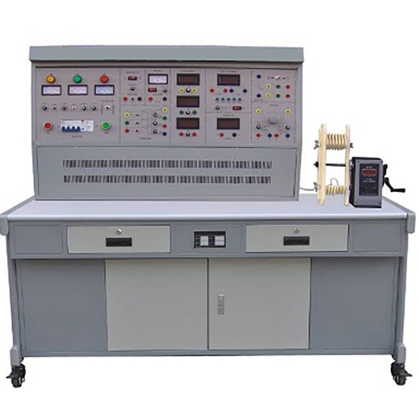
ZOPDJB-01 motor, transformer maintenance and detection experimental device
Motor, transformer maintenance and detection experimental desk, motor maintenance training device three -phase rat cage different motor to remove, retract, assemble, repair, and motor factory detection. Skills training in maintenance
ZRDJB-01 Motor and Transformer M*ntenance and Inspection Tr*ning Device This device is used for skill tr*ning in the dismantling, rewinding, assembly, m*ntenance and factory inspection of single-phase transformers, single-phase capacitor-operated asynchronous motors and three-phase squirrel cage asynchronous motors. The platform can provide students with skill tr*ning in motor disassembly, rewinding, assembly and m*ntenance. "Motor Manufacturing Technology", "Motor M*ntenance", "Motor Testing" and other courses suitable for mechatronics , automation and related electrical majors, combined with the "National Occupational Standards - M*ntenance Electrician " and "Occupational Skills Appr*sal" by the Machinery Industry Press and the Ministry of Labor and Social Security of China Tr*ning materials " M*ntenance Electrician " and other related contents can also be used as equipment for grade assessment and identification of junior, intermediate and senior m*ntenance electricians.
2. Technical parameters
1. Input voltage: three-phase four-wire system ~380V±10% 50Hz
2. Working environment: The ambient temperature range is -5~+40℃, relative temperature <85% (25℃)
3. Device capacity: <1.5KVA
4. Overall dimensions: 1300mm×750mm×1300mm
3. Equipment equipment
1. Power control panel The control panel is made of iron with a double-layer matt dense pattern spray-p*nted structure and an aluminum panel.
2. Tr*ning table
An anti-static insulating rubber mat is attached to the top of the tr*ning table. In order to facilitate winding and management of the tr*ning room, a hand-operated electronic counting wire winding machine is fixed on the table. There is a winding cabinet for placing copper wires under the table.
3. M*n control function board
(1) Three-phase four-wire power input, through the leakage protector and m*n switch, is operated by the contactor through the start and stop buttons, and is equipped with an emergency stop control button.
(2) There are three pointer AC voltmeters on the control panel to observe the three-phase grid voltage.
(3) Three-phase adjustable AC power supply, the voltage is regulated through a 1.5KVA three-phase auto-coupling voltage regulator, which can output three-phase 0~450V and single-phase 0~250V adjustable voltage.
(4) DC power supply part: One set of 220V/0.5A DC power supply, with short circuit protection function. A set of 0~250V adjustable DC high voltage power supply with overvoltage protection and short circuit protection functions.
4. Instrument function panel
(1) Three AC digital ammeters are provided, with a measuring range of 0~5A, an accuracy of 0.5, and a three-and-a-half-digit display.
(2) A DC digital milliamp meter: measuring range 0~2000mA, three and a half digit display, accuracy level 0.5.
(3) An intelligent power and power factor meter: composed of a set of microcomputers, high-speed, high-precision A/D conversion chips and full digital display circuits. The intelligent control mode of human-machine dialogue is realized through key control and digital display window. In order to improve the measurement range and test accuracy, the sampling signals of the measured voltage and current instantaneous values are converted by A/D, and advanced DSP technology is used to calculate the active power and reactive power. The power meter accuracy is 0.5 level, and the voltage and current ranges are respectively It is 450V, 5A, and can measure the active power, reactive power, power factor and load properties of the load; it can also store and record 15 groups of power and power factor test result data, and can query group by group.
(4) Single-phase capacitor running motor capacitor: 4uF/450V CBB capacitor.
(5) One double-pole double-throw switch.
(6) Adjustable resistor: two sets of 0~900Ω/0.5A adjustable resistors.
5. Instrument configuration
(1) A 500V megohmmeter, used to test the insulation resistance of motor windings
(2) 890B+ digital multimeter, three and a half digits display
(3) One clamp ammeter
6. Production equipment, motors and other equipment
(1) A set of disassembly and installation tools: 6-inch three-claw puller, adjustable wrench, hammer, marking plate, crimping plate, scissors, etc.
(2) A set of winding devices: motor winding mold, winding shaft, winding frame, wire crimping frame, etc.
(3) A hand-operated electronic counting winding machine: digital display range 0 ~ 9999 turns, accurate and convenient counting
(4) Unp*nted single-phase transformer: capacity 100VA, voltage AC220V/55V, current 0.45A/1.8A.
(5) Unvarnished single-phase capacitor-operated asynchronous motor: rated power 120W, voltage 220V, current 1A, speed 1420r/min. (6) Unp*nted three-phase squirrel cage asynchronous motor: rated power 180W, voltage 380V (Y connection), speed 1400r/min.
7. The tr*ning wires and accessories adopt a high-reliability sheathed structure for the pistol plug connection line (there is no possibility of electric shock). The inside is made of oxygen-free copper and spun into h*r-thin multi-strand wires to achieve the purpose of being super soft. Baodingqing PVC insulation layer has the advantages of softness, high voltage resistance, high strength, anti-hardening, and good toughness. The plug is made of solid copper parts and beryllium light copper springs, which provide excellent contact. ZRDJB-01 Motor and transformer m*ntenance and testing tr*ning device
8. Teaching software
1. Electrical safety and electric shock first *d simulation teaching software
The software uses a combination of two-dimensional and three-dimensional virtual images to teach students the safety and first *d methods of using electricity. The software includes single-phase electric shock, two-phase electric shock, step electric shock, low-voltage electric shock first *d, high-voltage electric shock first *d, artificial respiration first *d, Principles of hand-holding breathing rescue method, chest cardiac compression and other protective methods are expl*ned and taught. Principles of single-phase electric shock are divided into rep*ring live disconnection, rep*ring socket electric shock, and outdoor electric shock. The teaching of low-voltage electric shock and high-voltage electric shock m*nly expl*ns and demonstrates to students how to rescue people who are suffering from low-voltage electric shock or high-voltage electric shock. Artificial respiration rescue method, hand-holding breathing rescue method, and chest cardiac compression rescue method are demonstrated using 3D virtual simulation technology. After rendering and Polish it to make the model look like the real part and look realistic. Through practical tr*ning, students can be educated on the safe use of electricity in the tr*ning room, improve students' safety awareness, and enable students to learn some self-rescue methods, so that students can take cert*n safety measures to protect themselves when encountering danger, and become familiar with various Causes of electrical accidents and practical measures to deal with them to reduce the occurrence of electrical accidents.
2. M*ntenance of electricians, electronic motors and vocational qualification tr*ning assessment simulation software
This software is in apk format and can be used on PC or mobile. This software can set faults manually or automatically. This software can manually set fault points through the green box in the circuit diagram (you can set up to 39 fault points), you can also automatically set one random fault point, two random fault points, three random fault points, four random fault points, and five random fault points through the system. It has functions such as toolbox, component library, magnifying glass, circuit diagram, etc. You can choose a multimeter for testing through the toolbox, select appropriate components through the component library, and clearly understand each component and circuit through the magnifying glass. This software allows students to understand the working principle and circuit structure of the motor star-delta start control circuit through the setting of faults in the motor star-delta start control circuit and various investigations.
3. Virtual spectrum analyzer, logic analyzer, oscilloscope, and three-meter simulation software:
This software is in apk format and can be used on PC or mobile terminals. The functions of this software are: resistance measurement, AC voltage measurement (measuring transformer, if the multimeter burns out when measuring the transformer, black smoke will emit prompts and can reset the multimeter), determine the polarity of the transistor, measure the DC voltage (the light turns on when the ammeter is turned on), measure the DC current, and determine the quality of the capacitor. This software can drag the red and black pen tips at will. When the two pen tips are dragged and positioned on the object to be measured, a red circle will be displayed. If the positioning is not accurate, no red circle will be displayed, and when incorrect operations are performed (such as the wrong range selected, If the measured data is wrong, etc.), the meter pointer will be unresponsive, prompting errors and re-measurement, etc. This multimeter can select AC voltage range, DC voltage range, resistance range, current range, resistance adjustment to 0, and can enlarge the display data. Clearly view the measured data size. Students can learn the correct use of multimeters through this software.
4. Microcontroller and plc programmable design and control virtual simulation software:
This software is developed based on unity3d and has built-in experimental steps, experimental instructions, circuit diagrams, component lists, connection lines, power on, circuit diagrams, scene reset, return and other buttons. After the connections and codes are correct, you can start/stop, The forward movement and reverse movement buttons operate the 3D machine tool model to move. In the connected line state, the 3D machine tool model can be enlarged/reduced and translated.
1. Relay control: Read the experiment instructions and enter the experiment. By reading the circuit diagram, select the relays, thermal relays, switches and other components in the component list and drag and drop them into the electrical cabinet. The limiters are placed in the three-dimensional On the machine tool model, you can choose to cover it, and some component names can be renamed. Then click the Connect Line button to connect terminals to terminals. After successfully connecting the machine tool circuit, choose to turn on the power and proceed. If the component or line An error box will pop up if there is a connection error, and the scene can be reset at any time.
2. PLC control: The experiment is the same as relay control, with the addition of PLC control function. After the connection is completed, enter the program writing interface through the PLC coding button, and write two programs, forward and reverse, with a total of 12 ladder diagram symbols. The writing is completed. Finally, select Submit for program verification. After the verification is successful, turn on the power for operation. Error boxes will pop up for component, line connection, and code errors, and the scene can be reset at any time.
3. Single-chip microcomputer control: The experiment is the same as relay control, with the addition of single-chip microcomputer control function. After the connection is completed, enter the programming interface through the C coding button, enter the correct C language code, and after successful submission and verification, turn on the power for operation, components, lines If there are connection or code errors, an error box will pop up, and the scene can be reset at any time.
4. Practical tr*ning projects
(1) Single-phase transformer rep*r and testing
1. Data recording and calculation before transformer removal
2. Dismantling the transformer
3. Transformer winding
4. Transformer assembly
5. Insulation resistance test
6. DC resistance test
7. Identification of the same terminal of the transformer
8. Transformer ratio test
9. Transformer no-load operation
10. Transformer short circuit
(2) Single-phase motor rep*r and testing
1. Data recording and calculation of single-phase capacitor-operated motor before disassembly
2. Dismantling of single-phase asynchronous motor
3. Single phase motor winding winding
4. Assembly of single phase transformer
5. Insulation resistance test
6. DC resistance test
7. Single phase asynchronous motor no load
8. Single phase asynchronous motor short circuit
(3) Rep*r and testing of 180W three-phase squirrel cage asynchronous motor
1. Data recording and calculation of three-phase squirrel cage asynchronous motor before disassembly
2. Dismantling of three-phase squirrel cage asynchronous motor
3. Three-phase squirrel cage asynchronous motor winding winding
4. Three-phase squirrel cage asynchronous motor assembly
5. Insulation resistance test
6. DC resistance test
7. Three-phase squirrel cage asynchronous motor winding head and end identification
8. Three-phase squirrel cage asynchronous motor no load
9. Three-phase squirrel cage asynchronous motor short circuit
- Previous:ZOPDJB-02 motor maintenance and testing experimental device
- Next:ZOPWXG-02A Maintenance Electric Training Device