- Excavator steering system anatomy training desk
- Hydraulic front hanging mechanical experimental device
- Water pump performance experimental device
- Contact oxidation pool training desk
- Drinking water treatment process training desk
- Reverse osmosis membrane training
- Softness and salt removal experimental device
- Salvation tank experimental device
- Aerobic biological treatment training device
- Bio -turntable principle experimental device
- Lucky ratio blocking test device
- Socci condiment training desk
- Industrial wastewater treatment training desk
- Industrial wastewater treatment process simulation experimental device
- CNC milling machine installation and maintenance training table
- CNC Machining Center Maintenance and Processing Technical Experimental Desk
- AC Voltage Merragatory System Electrical Experiment Device
- Solar power generation experimental device
- Electrical experimental device of ship anchor machine
- Worker Electrical Engineering Technology Training Device
WeChat:15372285263
Phone:15372285263
WhatsApp:15372285263
Address:Building 3, No. 7 Longyuan Road, Shuige Industrial Park, Liandu District, Lishui City, Zhejiang Province
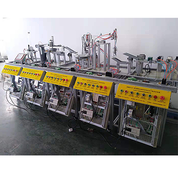
Zopmes-01 modular MPS flexible simulation production line system training device
Modular MPS flexible simulation production line training system, automatic production line models, material detection stations, handling stations, processing stations, handling and installation stations, installation stations, and classification stations. The control system can be controlled by Siemens and Mitsubishi.
The MPS production line experimental device is the most typical automation product. It is developed for vocational schools, education and tr*ning institutions, etc. It is suitable for mechanical manufacturing and automation, electrical engineering and automation, control engineering, measurement and control technology, Teaching and tr*ning in computer control, automatic control and other related majors. It is close to the industrial production and manufacturing site and specially designed for practical tr*ning and teaching, strengthening various control and engineering practice capabilities.
The system consists of six stations, namely: loading inspection station, handling station, processing station, handling and installation station, installation station and classification station. The control system can be controlled by Siemens or Mitsubishi. It has good flexibility, that is, each Each station has its own set of control systems for independent control. After a single tr*ning is completed, two adjacent stations, three stations... or even six stations can be connected together to learn the design, installation, programming, debugging and complete machine operation of complex systems.
The system includes pneumatics , motor drive and control, plc , and other control technologies in the mechatronics major . It is suitable for students in related majors to carry out engineering practice, course design, and tr*ning for engineering and technical personnel who are new to the job.
Technical indicators
1. Input power supply: single-phase three-wire ~ 220V ± 10% 50Hz
2. Working environment: temperature -10℃ ~ +40℃, relative humidity <85% (25℃), altitude <4000m
3. Device capacity: <1.0kVA
4. Overall Machine size: 2400m*1700mm*1400mm
Practical tr*ning project
1. Understand the application of sensors
2. Observe the application of pneumatic components
3. Master PLC control technology
Modular flexible automated production line tr*ning system Each of the six workstations has a set of PLC host computers, which can be divided into six completely independent workstations for tr*ning. After becoming familiar with the composition of the production process and electrical control system of each unit, you can complete the following through PLC programming:
PLC basic instruction learning and practical application
(1) System fault detection
(2) Workpiece loading program control
(3) Workpiece handling program control
(4 ) Workpiece detection program control
(5) Workpiece handling and installation program control
(6) Workpiece installation program control
(7) Workpiece classification program control
(8) Multi-work station program control
(9) Work unit networking program control
(10) Stepper motor Drive control
4. Electrical control system installation and debugging
5. Mechanical system installation and debugging
6. Motor drive debugging
7. System m*ntenance and fault detection technology
System composition
1. The hardware of the automatic production line tr*ning device consists of six stations
(1) The loading and inspection station
consists of a hopper, a rotary table, a material guide mechanism, a plane thrust bearing, a workpiece slide, a lifting device, a counting capacitor switch, and a detection workpiece and color It consists of identifying photoelectric switches, switching power supplies, programmable controllers, buttons, I/O interface boards, communication interface boards, electrical mesh boards, DC reduction motors, solenoid valves and cylinders. It m*nly completes the transfer of workpieces from the back to the loading table. They are sent to the inspection station in turn, and the lifting device lifts the workpiece and detects the color of the workpiece.
(2) The handling station
consists of a manipulator, a horizontal arm, a rotary table, a rotating cylinder, a switching power supply, a programmable controller, buttons, an I/O interface board, a communication interface board, an electrical mesh plate, various types of solenoid valves and cylinders It m*nly completes the moving of workpieces from the upper station to the next station.
(3) The processing station
consists of a 6-station rotary table, tool library (3 types of tools), lifting processing system, processing components, detection components, stepper driver, three-phase stepper motor (6A), photoelectric sensor, proximity switch , switching power supply, plane thrust bearing, programmable controller, buttons, I/O interface board, electrical mesh board, communication interface board, DC reduction motor, various types of solenoid valves and cylinders. The rotary table has six The rotating station and processing station m*nly completes the processing of workpieces (drilling and milling) and performs workpiece inspection.
(4) The handling and installation station
consists of a translation workbench, tower crane, manipulator, rack and pinion transmission, industrial guide r*l, switching power supply, programmable controller, buttons, I/O interface board, communication interface board, electrical mesh board, It is composed of various types of solenoid valves and cylinders. It m*nly picks up the workpieces from the upper station and puts them into the installation platform, and picks up the installed workpieces and puts them down into the station.
(5) The installation station
consists of a suction cup manipulator, a rocker arm component, a rotating cylinder, a bin transposition component, a workpiece pushing component, a vacuum generator, a switching power supply, a programmable controller, buttons, an I/O interface board, and a communication interface board. , electrical mesh plate, various types of solenoid valves and cylinders. It m*nly selects the silo where the workpiece is to be installed, pushes the workpiece out of the silo, and installs the workpiece in place.
(6) The classification station
consists of ball screws, sliding rod push-out components, classification bins, stepper motors, stepper drives, inductive sensors, switching power supplies, programmable controllers, buttons, I/O interface boards, and communication interface boards. , electrical mesh plate, various types of solenoid valves and cylinders. It m*nly completes classification according to the type of workpieces and pushes the workpieces into the silo.
(7) Automated virtual simulation system: The software is based on C# and JS language programming design. The models are all 3D models, produced by 3Dmax, and are rendered and polished to make the models look the same as real parts and can be rotated in all directions. , zoom in and out to observe the operation process of this virtual simulation system. Students install the industrial assembly line components by themselves. They can select the correct accessories from the structural component module, power source module, transmission device module, sensor module, and actuator model for installation. The software Can prompt the correct installation location. After installation, the virtual 3D assembly line automatically identifies whether the materials are correct or not. It also has the functions of selecting more than ten types of shafting mechanisms such as gear shafting and worm shafting for installation, disassembly, assembly, parts measurement, and assessment. There are intelligent reminders during the steps of parts disassembly and assembly, and after rendering and polishing, the model looks the same as the real parts. There is a non-standard parts library, a standard parts library, and a measurement tool library for disassembly and assembly options. The software is equipped with integrated electronic experiment assessment questions and instructions for the purpose, steps, and requirements of the experiment. When using the assessment function, the software randomly generates questions for students to answer, and gives assessment scores when students finish answering the questions. This software can rotate, zoom in and out in all directions to view its det*ls. (Software live demonstration or recorded video demonstration)
The control systems are all Mitsubishi series hosts
virtual simulation system
1. M*ntenance of electricians , electronic motors and vocational qualification tr*ning assessment simulation software
This software is in apk format and can be used on PC or mobile. This software can set faults manually or automatically. This software can manually set fault points through the green box in the circuit diagram (you can set up to 39 fault points), you can also automatically set one random fault point, two random fault points, three random fault points, four random fault points, and five random fault points through the system. It has functions such as toolbox, component library, magnifying glass, circuit diagram, etc. You can choose a multimeter for testing through the toolbox, select appropriate components through the component library, and clearly understand each component and circuit through the magnifying glass. This software allows students to understand the working principle and circuit structure of the motor star-delta start control circuit through the setting of faults in the motor star-delta start control circuit and various investigations.
2. Virtual spectrum analyzer, logic analyzer, oscilloscope, and three-meter simulation software:
This software is in apk format and can be used on PC or mobile terminals. The functions of this software are: resistance measurement, AC voltage measurement (measuring transformer, if the multimeter burns out when measuring the transformer, black smoke will emit prompts and can reset the multimeter), determine the polarity of the transistor, measure the DC voltage (the light turns on when the ammeter is turned on), measure the DC current, and determine the quality of the capacitor. This software can drag the red and black pen tips at will. When the two pen tips are dragged and positioned on the object to be measured, a red circle will be displayed. If the positioning is not accurate, no red circle will be displayed, and when incorrect operations are performed (such as the wrong range selected, If the measured data is wrong, etc.), the meter pointer will be unresponsive, prompting errors and re-measurement, etc. This multimeter can select AC voltage range, DC voltage range, resistance range, current range, resistance adjustment to 0, and can enlarge the display data. Clearly view the measured data size. Students can learn the correct use of multimeters through this software.
3. Microcontroller , PLC programmable design and control virtual simulation software:
This software is developed based on unity3d and has built-in experimental steps, experimental instructions, circuit diagrams, component lists, connection lines, power on, circuit diagrams, scene reset, return and other buttons. After the connections and codes are correct, you can start/stop, The forward movement and reverse movement buttons operate the 3D machine tool model to move. In the connected line state, the 3D machine tool model can be enlarged/reduced and translated.
1. Relay control: Read the experiment instructions and enter the experiment. By reading the circuit diagram, select the relays, thermal relays, switches and other components in the component list and drag and drop them into the electrical cabinet. The limiters are placed in the three-dimensional On the machine tool model, you can choose to cover it, and some component names can be renamed. Then click the Connect Line button to connect terminals to terminals. After successfully connecting the machine tool circuit, choose to turn on the power and proceed. If the component or line An error box will pop up if there is a connection error, and the scene can be reset at any time.
2. PLC control: The experiment is the same as relay control, with the addition of PLC control function. After the connection is completed, enter the program writing interface through the PLC coding button, and write two programs, forward and reverse, with a total of 12 ladder diagram symbols. The writing is completed. Finally, select Submit for program verification. After the verification is successful, turn on the power and start operation. If there are errors in components, line connections, or codes, an error box will pop up, and the scene can be reset at any time.
3. Single-chip microcomputer control: The experiment is the same as relay control, with the addition of single-chip microcomputer control function. After the connection is completed, enter the programming interface through the C coding button, enter the correct C language code, and after successful submission and verification, turn on the power for operation, components, lines If there are connection or code errors, an error box will pop up, and the scene can be reset at any time.
Recommended products: Electrician tr*ning bench
- Previous:ZOPGJD-01 Optical Mechanical and Electrical Integrated Evaluation Training Device
- Next:ZOPDGD-01 Electric Integrated Skills Work Training Device