- Excavator steering system anatomy training desk
- Hydraulic front hanging mechanical experimental device
- Water pump performance experimental device
- Contact oxidation pool training desk
- Drinking water treatment process training desk
- Reverse osmosis membrane training
- Softness and salt removal experimental device
- Salvation tank experimental device
- Aerobic biological treatment training device
- Bio -turntable principle experimental device
- Lucky ratio blocking test device
- Socci condiment training desk
- Industrial wastewater treatment training desk
- Industrial wastewater treatment process simulation experimental device
- CNC milling machine installation and maintenance training table
- CNC Machining Center Maintenance and Processing Technical Experimental Desk
- AC Voltage Merragatory System Electrical Experiment Device
- Solar power generation experimental device
- Electrical experimental device of ship anchor machine
- Worker Electrical Engineering Technology Training Device
WeChat:15372285263
Phone:15372285263
WhatsApp:15372285263
Address:Building 3, No. 7 Longyuan Road, Shuige Industrial Park, Liandu District, Lishui City, Zhejiang Province
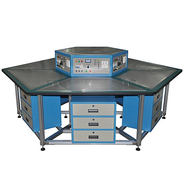
ZOPDGD-01 Electric Integrated Skills Work Training Device
Electrician integrated skills work island, the entire control screen of the 6 -station electrical skills training platform is composed of the six -site station. Each station has a startup and stop button to control the output of the power supply, and there is an emergency stop button. Short circuit protection.
1. Working power supply: three-phase five-wire AC380V ±5% 50Hz
2. Safety protection: leakage protection (action current ≤30mA), overcurrent protection, fuse protection;
3. Rated power: ≤2KW;
4. Ambient temperature: - 10℃~40℃;
5. Relative humidity: ≤85%;
2. Configuration technical parameters:
1. Desk body part: It is made of high-quality steel plate as the skeleton, which is machined and formed. The outer surface is sprayed with colorful epoxy polyplastic. The whole machine is both sturdy and durable, and beautiful and elegant. The bottom of the table uses universal wheels with brakes to facilitate adjustment of the placement of the equipment.
2. Desktop part: Made of 25mm thick high-density fiberboard with imported fireproof board and PVC cross-section edge sealing. The desktop is wear-resistant, heat-resistant, st*n-resistant, smoke-resistant, fire-resistant, bacteria-resistant, mildew-resistant, anti-static and easy to clean.
3. Practical tr*ning screen part: The whole adopts steel frame structure. The frame is made of high-quality steel, which is machined and shaped, and the outer surface is sprayed with colored epoxy polyplastic. According to different tr*ning and identification projects, various types of power supplies are integrated and equipped. The text symbols on the operation panel are clear and durable.
The entire control panel consists of six stations. Each station is equipped with start and stop buttons to control the output of the power supply, and is equipped with an emergency stop button. The power output is short-circuit protected. At the same time, there is a 450V pointer type AC voltmeter, which can indicate the three-phase line voltage of the power input by switching the band switch.
4. Multi-function mesh board part: The multi-function mesh board adopts a mesh layout design. The m*n body is processed and formed from a 1.5mm thick brushed st*nless steel plate. It is processed with 5X10mm holes and is matched with fixed rubber clips. The overall design is standardized and reasonable, making all kinds of Components can be easily assembled and adjusted at any angle and in any orientation.
5. Virtual simulation system
1. M*ntenance of electricians , electronic motors and vocational qualification tr*ning assessment simulation software
This software is in apk format and can be used on PC or mobile. This software can set faults manually or automatically. This software can manually set fault points through the green box in the circuit diagram (you can set up to 39 fault points), you can also automatically set one random fault point, two random fault points, three random fault points, four random fault points, and five random fault points through the system. It has functions such as toolbox, component library, magnifying glass, circuit diagram, etc. You can choose a multimeter for testing through the toolbox, select appropriate components through the component library, and clearly understand each component and circuit through the magnifying glass. This software allows students to understand the working principle and circuit structure of the motor star-delta start control circuit through the setting of faults in the motor star-delta start control circuit and various investigations.
2. Virtual spectrum analyzer, logic analyzer, oscilloscope, and three-meter simulation software:
This software is in apk format and can be used on PC or mobile terminals. The functions of this software are: resistance measurement, AC voltage measurement (measuring transformer, if the multimeter burns out when measuring the transformer, black smoke will emit prompts and can reset the multimeter), determine the polarity of the transistor, measure the DC voltage (the light turns on when the ammeter is turned on), measure the DC current, and determine the quality of the capacitor. This software can drag the red and black pen tips at will. When the two pen tips are dragged and positioned on the object to be measured, a red circle will be displayed. If the positioning is not accurate, no red circle will be displayed, and when incorrect operations are performed (such as the wrong range selected, If the measured data is wrong, etc.), the meter pointer will be unresponsive, prompting errors and re-measurement, etc. This multimeter can select AC voltage range, DC voltage range, resistance range, current range, resistance adjustment to 0, and can enlarge the display data. Clearly view the measured data size. Students can learn the correct use of multimeters through this software.
3. Microcontroller and plc programmable design and control virtual simulation software:
This software is developed based on unity3d and has built-in experimental steps, experimental instructions, circuit diagrams, component lists, connection lines, power on, circuit diagrams, scene reset, return and other buttons. After the connections and codes are correct, you can start/stop, The forward movement and reverse movement buttons operate the 3D machine tool model to move. In the connected line state, the 3D machine tool model can be enlarged/reduced and translated.
1. Relay control: Read the experiment instructions and enter the experiment. By reading the circuit diagram, select the relays, thermal relays, switches and other components in the component list and drag and drop them into the electrical cabinet. The limiters are placed in the three-dimensional On the machine tool model, you can choose to cover it, and some component names can be renamed. Then click the Connect Line button to connect terminals to terminals. After successfully connecting the machine tool circuit, choose to turn on the power and proceed. If the component or line An error box will pop up if there is a connection error, and the scene can be reset at any time.
2. PLC control: The experiment is the same as relay control, with the addition of PLC control function. After the connection is completed, enter the program writing interface through the PLC coding button, and write two programs, forward and reverse, with a total of 12 ladder diagram symbols. The writing is completed. Finally, select Submit for program verification. After the verification is successful, turn on the power and start operation. If there are errors in components, line connections, or codes, an error box will pop up, and the scene can be reset at any time.
3. Single-chip microcomputer control: The experiment is the same as relay control, with the addition of single-chip microcomputer control function. After the connection is completed, enter the programming interface through the C coding button, enter the correct C language code, and after successful submission and verification, turn on the power for operation, components, lines If there are connection or code errors, an error box will pop up, and the scene can be reset at any time.
3. Tr*ning instruments and motors
1. Three-phase squirrel cage asynchronous motor
①AC380V/△;
②6 units/set.
2. Three-phase squirrel-cage asynchronous motor
①AC380V/Y;
②With speed relay;
③3 sets/set.
3. Three-phase two-speed asynchronous motor
①AC380V/YY/△;
②6 units/set.
4. Provide 6 sets/set of practical tr*ning instruments such as multimeters, megohmmeters, and clamp ammeters.
4. Practical tr*ning projects
1. Basic skills tr*ning:
①The use and identification of commonly used tools;
②Electrician diagram recognition tr*ning;
③Electrical wiring technology;
④Connection of commonly used wires and restoration of insulation layers;
⑤Knowledge and use of multimeters;
⑥Knowledge and use of megohmmeters;
⑦Clamp ammeter understanding and use.
2. Electric drag tr*ning:
① Three-phase asynchronous motor direct start control;
② Three-phase asynchronous motor contactor inching control circuit;
③ Three-phase asynchronous motor contactor self-locking control circuit;
④ Three-phase asynchronous motor Y-△ start Manual control circuit;
⑤ Three-phase asynchronous motor Y-△ start automatic control circuit;
⑥ Three-phase asynchronous motor contactor interlocking forward and reverse control circuit;
⑦ Three-phase asynchronous motor button interlocking forward and reverse control circuit;
⑧ Three Double interlocked forward and reverse control circuit of phase asynchronous motor;
⑨ forward and reverse control circuit of reverse switch control of three-phase asynchronous motor;
⑩ energy consumption braking control circuit of four- and three-phase asynchronous motor;
⑪ reverse connection system of three-phase asynchronous motor
⑫Three-phase asynchronous motor series resistance step-down starting control circuit; ⑬Three
-phase asynchronous motor multi-site control circuit;
⑭Workbench automatic round-trip control circuit;
⑮Contactor-controlled three-phase two-speed asynchronous motor control circuit;
⑯ Three-phase two-speed asynchronous motor control circuit controlled by time relay;
⑰Students design the installation, wiring and debugging of the circuit by themselves.
3. Instrument lighting tr*ning:
①Installation of incandescent lighting circuit;
②Two switches control one light;
③Two places control one light;
④Voice-activated switch controls lighting circuit;
⑤Human body sensor switch controls lighting circuit;
⑥Touch delay switch controls lighting circuit;
⑦ Fluorescent lamp circuit;
⑧Principle and wiring of electricity meter;
⑧Direct wiring of single-phase electricity meter;
⑨Wiring of single-phase electricity meter through current transformer;
⑩Residential lighting circuit tr*ning.
Hot-selling product: Electrician tr*ning bench
- Previous:Zopmes-01 modular MPS flexible simulation production line system training device
- Next:ZOPDG-WS maintenance electrical comprehensive training device