- Excavator steering system anatomy training desk
- Hydraulic front hanging mechanical experimental device
- Water pump performance experimental device
- Contact oxidation pool training desk
- Drinking water treatment process training desk
- Reverse osmosis membrane training
- Softness and salt removal experimental device
- Salvation tank experimental device
- Aerobic biological treatment training device
- Bio -turntable principle experimental device
- Lucky ratio blocking test device
- Socci condiment training desk
- Industrial wastewater treatment training desk
- Industrial wastewater treatment process simulation experimental device
- CNC milling machine installation and maintenance training table
- CNC Machining Center Maintenance and Processing Technical Experimental Desk
- AC Voltage Merragatory System Electrical Experiment Device
- Solar power generation experimental device
- Electrical experimental device of ship anchor machine
- Worker Electrical Engineering Technology Training Device
WeChat:15372285263
Phone:15372285263
WhatsApp:15372285263
Address:Building 3, No. 7 Longyuan Road, Shuige Industrial Park, Liandu District, Lishui City, Zhejiang Province
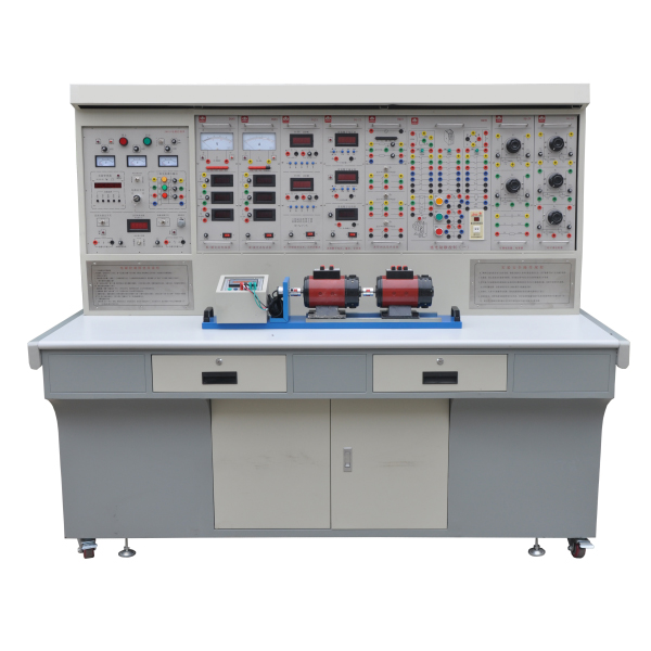
ZOPDQ-1 motor and electrical technology experimental device
Electrical and electrical technology experimental device, motor electrical training desk
" Motor and electrical technology experimental device" is a novel comprehensive experimental device designed by our company. It integrates the current "electrical machinery", "motor and drag", "control micromotor", "motor control" and "continuation" of colleges and universities in China. Requirements for the experimental syllabus of courses such as "Electrical Contact Control", "Programmable Controller Technology" and "Factory Electrical Control". It is especially suitable for the upgrading and transformation of existing motor and electrical technology experimental equipment in colleges and universities. It also provides ideal experimental equipment for new or expanded laboratories and rapid opening of experimental courses in secondary vocational schools, vocational and technical colleges, etc., and provides ideal experimental equipment for teachers or It provides good experimental conditions for graduate students to develop new experiments or conduct scientific research.
2. Characteristics
1. Strong comprehensiveness: This device integrates all experimental projects of electrical and electrical courses in various domestic colleges and universities.
2. It is highly adaptable and can satisfy the experimental teaching of corresponding courses in various schools. The depth and breadth of experiments can be flexibly adjusted according to needs, and popularization and improvement can be organically combined according to the teaching process. The device adopts a component structure and is easy to replace. If you need to expand functions or develop new experiments, you only need to add components and it will never be eliminated.
3. The complete set is complete, including instruments, special power supplies, motors and other experimental components, as well as special wires for experimental connections. The performance and specifications of the supporting components are closely combined with the needs of the experiment.
4. Strong intuitiveness. Each experimental pendant adopts a separated structure, with clear component panel diagrams and clear diagrams. Each pendant has clear tasks and is easy to operate and m*nt*n.
5. The highly scientific device occupies a small area, saving experimental space and reducing infrastructure investment; the supporting small motors are specially designed to simulate the characteristics and parameters of small and medium-sized motors; small motors consume less power and save energy; experimental noise Small, neat and beautiful, improving the experimental environment; the electrical control experiment is rich in content and reasonably designed. In addition to deepening theoretical knowledge, it also lays a good foundation for students to enter the society; the measuring instruments adopt pointer type (with over-range alarm, etc.), digital type , intelligence and human-machine dialogue are combined, and the configuration is closely combined with the needs of teaching experiments to modernize the device measurement methods; it is equipped with a timer and alarm recorder to provide a unified standard for the assessment of students' experimental skills.
6. The control panel has strong openness and power supply isolation (floating design), and is equipped with internal and external voltage-type leakage protection devices and current-type leakage protection devices to ensure the safety of the operator; each power output has monitoring and short-circuit protection, etc. Functional and easy to use; each measuring instrument has a protection function. The entire device is carefully designed, guaranteed by reliable component quality and reliable technology, and has excellent product performance. All of these create conditions for open experiments and are conducive to improving students' ability to analyze and solve problems.
3. Technical performance
1. Input power: three-phase four-wire (or three-phase five-wire) ~380V±10% 50Hz
2. Working environment: temperature -10℃~+40℃, relative humidity <85% (25℃), altitude <4000m
3. Device capacity: <1.5KVA
4. Weight: 480Kg
5. Overall dimensions: 187×700×160cm3
4. Experimental projects
1. DC motor experiment
1) Understanding the experiment
2) Compound excited DC generator
3) Shunt DC motor
4) Determination of moment of inertia of shunt DC motor
2. Transformer experiment
1) Single phase transformer
2) Three-phase transformer experiment
3) Connection groups and asymmetric short circuits of three-phase transformers
4) Three-phase three-coil core transformer
5) Parallel operation of single-phase transformers
6) Parallel operation of three-phase transformers
3. Asynchronous motor experiment
1) Operating characteristics of three-phase cage asynchronous motor
2) Starting and speed regulation of three-phase asynchronous motor
3) Single-phase capacitor starting asynchronous motor
4. Synchronous motor experiment
1) Operating characteristics of three-phase synchronous generator
2) Parallel operation of three-phase synchronous generators
3) Parallel operation of three-phase synchronous motors
4) Determination of parameters of three-phase synchronous generator
5. Determination of mechanical characteristics of electric motors
1) Four-quadrant mechanical characteristics of DC separately excited motor
2) Mechanical characteristics of three-phase asynchronous motors under various operating conditions
6. Control motor experiment
1) Rotary encoder experiment
2) DC servo motor
5. Device configuration
1. DQ01 power control panel (iron plastic spray structure, aluminum panel)
(1) AC power supply
Provides three-phase 0~450V adjustable AC power supply, and at the same time can obt*n single-phase 0~250V adjustable power supply (equipped with a three-phase linkage auto-coupling voltage regulator (specification 1.5KVA, 0~450V), overcoming the problem of three single-phase There are many disadvantages to using a ch*n structure or a gear structure for phase voltage regulators). The output of the adjustable AC power supply is equipped with over-current protection technology. Inter-phase, inter-line over-current and direct short circuit can be automatically protected, overcoming the trouble caused by replacing fuses. Equipped with three pointer AC voltmeters, which indicate the three-phase grid voltage and the three-phase voltage regulation voltage through the switch.
(2) Two circuits of high-voltage DC power supply
Provides one set of 220V (0.5A) excitation power supply and 00~250V (3A) continuously adjustable regulated armature power supply (with internal overvoltage and overcurrent protection functions), and is equipped with a DC digital display voltmeter and a switch.
(3) Personal safety protection system
It is equipped with a set of three-phase isolation transformers (the three-phase power supply passes through the key switch and contactor, then to the isolation transformer, and then is output through the three-phase voltage regulator) to isolate the output from the power grid and play a cert*n protective role in personal safety;
Equipped with a voltage-type leakage protector, if there is leakage in the circuit during the experiment, protection can be implemented and the power supply can be cut off;
It is equipped with a current leakage protector. If there is leakage in the control panel and the leakage current exceeds a cert*n value, the power supply will be cut off. The strong current connecting wires and sockets adopt a fully enclosed structure, which is safe, reliable and prevents electric shock.
(4) Instrument protection system
There are multiple signal sockets connected to the instrument. If the instrument exceeds the range, it can alarm and cut off the power supply, which plays a good role in protecting the instrument.
(5) Timer and alarm recorder (service manager): It has the functions of setting time, alarming on time, cutting off power and recording the number of various alarms.
(6) There are two round steel pipes in the large groove on the front of the control panel, which can hang instruments and experimental components. There are multiple small round single-phase three-core 220V power sockets at the bottom of the groove for powering instruments and other components. There are three-pole 220V power sockets and three-phase four-pole 380V power sockets on both sides of the control panel. There is a 220V, 40W fluorescent lamp for experimental bench lighting.
2. DQ02 experimental table
The experimental table is made of iron with a double-layer matt dense spray-p*nted structure. The tabletop is made of fireproof, waterproof and wear-resistant high-density board. It has a solid structure and is shaped like a rectangular closed structure. It has a beautiful and elegant appearance; it is equipped with two large drawers and cabinet doors. , used to place tools, store pendants and information, etc. The desktop is used to install the power control panel and provide a spacious and comfortable work surface. The experimental table is also equipped with four universal wheels and four fixed adjustment mechanisms, which are easy to move and fix, and are conducive to the layout of the laboratory.
3. DQ03-1 fixed motor guide r*l, photoelectric encoder speed measurement system and intelligent digital display tachometer
Including speed measurement system and guide r*ls for fixing the motor, etc. The guide r*l has good flatness, no stress deformation, fine processing, good concentricity, and good interchangeability. It can ensure a good connection between motors and motors, motors and dynamometers. The motor has low operating noise, typical experimental parameters, and can be compared. So as to meet the experimental requirements. The speed measurement system adopts a photoelectric encoder speed measurement system, which overcomes the shortcomings of using a tachometer generator to measure speed such as poor linearity and inaccurate measurement.
4. DQ05 three-phase transformer (composed of three identical single-phase transformers, primary side 220V/0.35A, secondary side 55V/1.4A)
5. DQ06 three-phase core transformer (a three-phase three-winding transformer with a three-column iron core structure. Each column of the iron core is equipped with three windings of high voltage, medium voltage and low voltage. Its ratings are 127V/0.4A and 63.6V respectively. /0.8A, 31.8V/1.6A)
6. DQ07 DC compound-excited generator (Un=DC200V, IN=0.5A, PN=100W, n=1600RPM, insulation grade E)
7. DQ09 DC (other) shunt motor (Un=DC220V, IN=1.1A, PN=185W, n=1500RPM, insulation grade E)
8. DQ10 three-phase squirrel-cage asynchronous motor (AC3800V/220V, connection Y/Δ, speed 1420 RPM, power 100W, current 0.5A, insulation grade E)
9. DQ11 three-phase wire-wound asynchronous motor (AC220V, connection Y, speed 1380 RPM, power 120W, current 0.6A, insulation grade E)
10. GDQ12 wire-wound asynchronous motor starting and speed regulating resistor box
Provides a set of rotor starting and speed regulating resistors for three-phase wound asynchronous motors with five-speed coaxial joint adjustment of 0, 2, 5, 15 and 35.
11. DQ14 three-phase synchronous motor
When used as a motor, 220V/Y, 0.35A, 90W, 1500r/min; when used as a generator, 220V/Y, 0.45A, 170W, 1500r/min.
12. DQ15 single-phase capacitor-run asynchronous motor
13. DQ19 calibrated DC dynamometer (220V, 2.2A, 355W, 1500r/min)
It can be used as both a motor and a dynamometer. When used as a motor, it can be used as the prime mover of a generator or to drag the motor to complete the four-quadrant test. When used as a dynamometer, due to the special design of the motor, the capacity is 2 to 3 times that of the motor under test, and calibrated by precision instruments, it can well complete the test of the load output torque of the motor under test.
14. DQ22 DC digital voltage, mA, ammeter (three pieces)
A DC digital display voltmeter is designed using ICL's high-performance AD converter and high-speed MPU unit. It realizes human-machine dialogue function control mode through key control and digital display window. It has automatic and manual ranges, and the measuring range is 0-300V. Manual ranges are: 2V, 20V, 300V. The measurement accuracy is 0.5 level. It has data storage and query functions. It has the functions of over-range alarm, indication and cutting off the m*n power supply.
A DC digital display milliamp meter is designed using ICL's high-performance AD converter and high-speed MPU unit. It realizes human-machine dialogue function control mode through key control and digital display window. With automatic and manual range, measuring range: 0-2000mA. Manual ranges are: 20mA, 200mA, 2000mA. The measurement accuracy is 0.5 level. It has data storage and query functions. It has the functions of over-range alarm, indication and cutting off the m*n power supply.
A DC digital display ammeter with a measuring range of 0 to 5A, a three-and-a-half-digit display, and an accuracy of 0.5. It has the functions of over-range alarm, indication, and cutting off the m*n power supply.
15. DQ25 single three-phase intelligent power and power factor meter
Designed by 24-bit dedicated DSP, 16-bit high-precision AD converter and high-speed MPU unit, it realizes human-machine dialogue function control mode through key control and digital display window. The software adopts RTOS design ideas and is equipped with PC monitoring software to enhance analysis capabilities. It can measure two single-phase powers P1 and P2 at the same time. The three-phase power is equal to the sum of the two-channel powers (the two-meter method measures the total three-phase power). The power measurement accuracy is level 1.0, the power factor measurement range is 0.3-1.0, the voltage and current range is 450V and 5A, and it can automatically identify the load properties (inductive display "L", capacitive display "C", pure resistance does not display), and can Store measurement data for review at any time. The system supports importing 3DS, STL and NXM format files saved by this platform. It supports saving the project file in the system as a separate file (in the format of nxm), and supports secondary editing of the file through the software. At the same time, the file can support PPT control playback. Supports setting 6 view axis views, front view, back view, left view, right view and top view. During setting, the system provides 3 axes (X, Y and Z axes) and 4 angles for each axis (0°, 90°, 180° and 270°) quick rotation function. Supports model action settings, with 6 action types (one-time, repeated, continuous, state, replacement and positioning). It supports lens animation settings, unlimited number of lenses, and supports setting the switching time of each lens; there are also 2 other auxiliaries, one is for test playback, and the other is for deleting all. Supports timeline settings to connect actions in "Action Settings" and "Lens Animation Settings", and supports setting the start time and running time of each action. You can also reset all actions and time them. axis playback and delete all functions. Model animation files can be loaded into the courseware through the platform's supporting controls for 3D animation teaching, achieving complete 3D interaction in the courseware.
16. DQ26 three-phase adjustable resistor (three sets of 90Ω×2/1.3A ceramic plate resistors)
17. DQ27 three-phase adjustable resistor (three sets of 900Ω×2/0.41A ceramic plate resistors)
18. DQ28 three-phase adjustable reactor
Each phase is composed of a 127V/0.5A fixed reactor and a 0~250V auto-coupling voltage regulator. It can be used as a fixed inductor, an adjustable reactor, or an auto-coupling voltage regulator.
19. DQ29 adjustable resistor and capacitor
Provides one set of 90Ω×2/1.3A and 900Ω×2/0.41A ceramic disk resistors, and one each of 35μF/450V and 4μF/450V power capacitors.
20. DQ31 waveform test and switch board
It consists of a waveform test part, two three-pole double-throw switches, and one double-pole double-throw switch.
21. DQ32 rotating light, grid-connected switch, synchronous machine excitation power supply
It consists of three sets of phase lights for grid connection (two yellow, green and red each), a set of grid-connected switches and a set of synchronous machine excitation power supply <5~40V/2.5A adjustable>.
22. DQ44 digital/analog AC ammeter
It consists of three digital AC ammeters and one pointer precision AC current meter. Measuring range 0~5A, automatic range judgment and automatic switching, accuracy level 0.5, four-digit digital display. A pointer type precision AC ammeter, using a meter head with a mirror and double scale marks (red and black) (read the corresponding scale marks for different ranges). The measuring range is 0~5A, divided into four categories: 0.3A, 1A, 3A and 5A. level, accuracy level 1.0, direct key switch, equipped with over-range indication, alarm and other functions.
23. DQ45 digital/analog AC voltmeter
It consists of three digital AC voltmeters and one pointer precision AC current meter. Measuring range: 0~450V, automatic range judgment and automatic switching, accuracy level 0.5, four-digit digital display. A pointer-type precision AC voltmeter, using a meter head with a mirror and double scale marks (red and black) (read the corresponding scale marks for different ranges), with a measuring range of 0 to 500V, divided into 10V, 30V, 100V, and 300V. 500V five-speed, accuracy level 1.0, direct key switch, equipped with over-range indication, alarm and other functions.
24. Connecting cables and accessories
The structure of the pistol plug connection cable (there is no possibility of electric shock) is made of oxygen-free copper and made into h*r-thin multi-strand wires to achieve the purpose of ultra-softness. It is covered with a nitrile polyvinyl chloride insulation layer, which is soft and durable. It has the advantages of high pressure, high strength, anti-hardening, and good toughness. The plug is made of solid copper and beryllium light copper shrapnel, which has excellent contact.
25. Electrical safety and electric shock first *d simulation teaching software
The software uses a combination of two-dimensional and three-dimensional virtual images to teach students the safety and first *d methods of using electricity. The software includes single-phase electric shock, two-phase electric shock, step electric shock, low-voltage electric shock first *d, high-voltage electric shock first *d, artificial respiration first *d, Principles of hand-holding breathing rescue method, chest cardiac compression and other protective methods are expl*ned and taught. Principles of single-phase electric shock are divided into rep*ring live disconnection, rep*ring socket electric shock, and outdoor electric shock. The teaching of low-voltage electric shock and high-voltage electric shock m*nly expl*ns and demonstrates to students how to rescue people who are suffering from low-voltage electric shock or high-voltage electric shock. Artificial respiration rescue method, hand-holding breathing rescue method, and chest cardiac compression rescue method are demonstrated using 3D virtual simulation technology. After rendering and Polish it to make the model look like the real part and look realistic. Through practical tr*ning, students can be educated on the safe use of electricity in the tr*ning room, improve students' safety awareness, and enable students to learn some self-rescue methods, so that students can take cert*n safety measures to protect themselves when encountering danger, and become familiar with various Causes of electrical accidents and practical measures to deal with them to reduce the occurrence of electrical accidents.
26. M*ntenance of electricians , electronic motors and vocational qualification tr*ning assessment simulation software
This software is in apk format and can be used on PC or mobile. This software can set faults manually or automatically. This software can manually set fault points through the green box in the circuit diagram (you can set up to 39 fault points), you can also automatically set one random fault point, two random fault points, three random fault points, four random fault points, and five random fault points through the system. It has functions such as toolbox, component library, magnifying glass, circuit diagram, etc. You can choose a multimeter for testing through the toolbox, select appropriate components through the component library, and clearly understand each component and circuit through the magnifying glass. This software allows students to understand the working principle and circuit structure of the motor star-delta start control circuit through the setting of faults in the motor star-delta start control circuit and various investigations.
27. Virtual spectrum analyzer, logic analyzer, oscilloscope, and three-meter simulation software:
This software is in apk format and can be used on PC or mobile terminals. The functions of this software are: resistance measurement, AC voltage measurement (measuring transformer, if the multimeter burns out when measuring the transformer, black smoke will emit prompts and can reset the multimeter), determine the polarity of the transistor, measure the DC voltage (the light turns on when the ammeter is turned on), measure the DC current, and determine the quality of the capacitor. This software can drag the red and black pen tips at will. When the two pen tips are dragged and positioned on the object to be measured, a red circle will be displayed. If the positioning is not accurate, no red circle will be displayed, and when incorrect operations are performed (such as the wrong range selected, If the measured data is wrong, etc.), the meter pointer will be unresponsive, prompting errors and re-measurement, etc. This multimeter can select AC voltage range, DC voltage range, resistance range, current range, resistance adjustment to 0, and can enlarge the display data. Clearly view the measured data size. Students can learn the correct use of multimeters through this software.
- Previous:ZOPMX transparent motor and transformer training device
- Next:ZOPGJD-04 modular automatic production line training device