News
News
- Excavator steering system anatomy training desk
- Hydraulic front hanging mechanical experimental device
- Water pump performance experimental device
- Contact oxidation pool training desk
- Drinking water treatment process training desk
- Reverse osmosis membrane training
- Softness and salt removal experimental device
- Salvation tank experimental device
- Aerobic biological treatment training device
- Bio -turntable principle experimental device
- Lucky ratio blocking test device
- Socci condiment training desk
- Industrial wastewater treatment training desk
- Industrial wastewater treatment process simulation experimental device
- CNC milling machine installation and maintenance training table
- CNC Machining Center Maintenance and Processing Technical Experimental Desk
- AC Voltage Merragatory System Electrical Experiment Device
- Solar power generation experimental device
- Electrical experimental device of ship anchor machine
- Worker Electrical Engineering Technology Training Device
Contact us
WeChat:15372285263
Phone:15372285263
WhatsApp:15372285263
Address:Building 3, No. 7 Longyuan Road, Shuige Industrial Park, Liandu District, Lishui City, Zhejiang Province
News
Elevator electrical control training device
Author:
Time:2024-01-05
Hits:
Elevator electrical control tr--ning device,Digital Electric Modeling Experiment
1. Overall requirements

Elevator electrical control tr--ning device,Digital Electric Modeling Experiment
1. Overall requirements
1. The model elevator has 4 floors and 4 stations. It consists of analogytic road frame, car, p--r, dictation machine, elevator door, door motor, out -of -floor call box, and m--n safety devices. The fixed setting is set on the side of the experimental table. The internal demand of analogyard frame is configured to detect floor sensors, flat layers (similar to actual elevators), etc. Its wiring terminals are cited to the inserted holes of the simulated manhole frame. The manhole frame uses metal materials as the m--n bracket, and organic glass is closed.
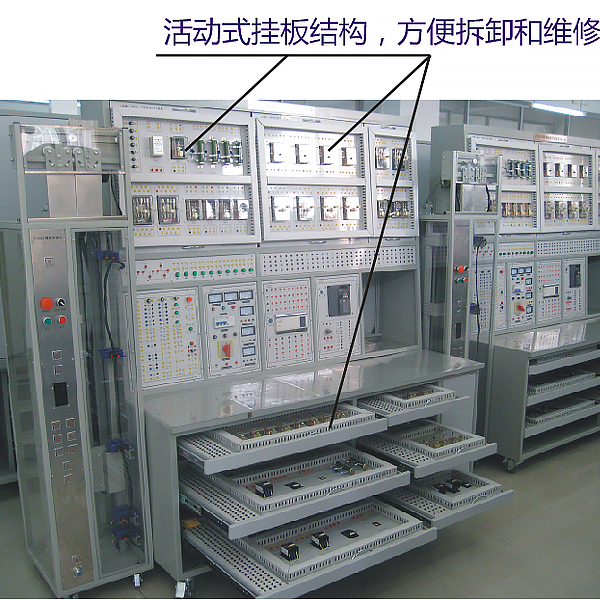
The device adopts a desktop structure, and the active drawer electrical board is set. Each layer drawer board is equipped with a public wiring board (bus -type wiring method, the number of bus connection points must reach 120 points), and the industrial tank ch--n connection is used between the drawer electrical board. The drawer panel connection uses a real elevator multi -core accompanying cable.
2. Model elevator drag system
The model elevator drag system is fixed on the experimental table, consisting of three -phase AC motors, reducers, fuses, heating relays, phase sequences and disconnecting relays, and AC contactors used for positive and reverse control. 380V.
3. Elevator door control system
The elevator door control system consists of the switching door control circuit and door speed adjustment circuit. The door motor is fixed on the analog manhole frame, and the DC 24V is powered. Control in relay and use independent hanging boards, which can achieve manual or automatic control of the door.

Elevator electrical control tr--ning device,Digital Electric Modeling Experiment
1. The characteristics of the product:
The experimental table has more comprehensive safety protection measures and more complete functions. The center of the experimental table is equipped with a universal circuit board, and the circuit board is injected into injection. The surface cloth has porous into a set of connecting jacks. The component box is freely inserted into an experimental circuit. The intuitiveness is good. Component symbols, clear and beautiful lines. The box body and the lid adopt a more scientific card structure, which is convenient for m--ntenance and disassembly. The components are placed in the left and right cabinets under the experimental table, which greatly improves the level of management and the degree of planning, which greatly reduces the preparation of teachers' experiment.
2. Experimental table and operating table structure:
1. Experiment table shell size: 123 × 35 × 20cm
2. Three -phase insurance seat
3. Three -phase power input indicator
4. Total switch: Total switch of the experiment platform, leakage and overload protection
5. Test button: Test leakage switching leakage function
6. Power input indicator 1
7. The power supply output indicator 3 (red, green, yellow three color)
8. AC voltage table: indicate output cable voltage
9. Voltage conversion switch: Combined with the voltage meter, monitor the size and symmetry of the output cable voltage
10. 5 Wiring seats: Unit A, three -phase, four lines and ground line output
11. Current meter W phase current output instruction
12. O/i switch: three -phase four -wire power supply output control
(Improve the safety factor)
13. Two wiring seats: Union B AC low -voltage power output
14. Power Table (2A): Unit B AC current instructions
15. Knob: Union B 3-24V AC low pressure selection output
16. Switch: Union C Drinks DC voltage voltage pressure power switch
17. Knob: Union C dual road Ⅰ road steady stream adjustment
18. Knob: Union C, Double Road II Road Stabilization Adjustment
19. Two wiring seats: Unit C Road Ⅰ DC stabilization output
20. Insurance seat: Union C dual -road voltage pressure power insurance
twenty one. 4 meters: dual -road voltage power supply voltage, current indication
twenty two. Wiring seat: Union D DC 5V Voltage Output
twenty three. Electric meter: Union D current 0.5V output instructions
twenty four. Switch 1: Control each low -voltage AC power and signal source
25. Switch 2: Control the DC pressure regulation power supply
26. Electric meter: Unit A AC voltage output instructions
- Previous:Comprehensive test training device of motor performance
- Next:Elevator door system disassembly training device
Recommended information
Recommended Products