Product
News
- Excavator steering system anatomy training desk
- Hydraulic front hanging mechanical experimental device
- Water pump performance experimental device
- Contact oxidation pool training desk
- Drinking water treatment process training desk
- Reverse osmosis membrane training
- Softness and salt removal experimental device
- Salvation tank experimental device
- Aerobic biological treatment training device
- Bio -turntable principle experimental device
- Lucky ratio blocking test device
- Socci condiment training desk
- Industrial wastewater treatment training desk
- Industrial wastewater treatment process simulation experimental device
- CNC milling machine installation and maintenance training table
- CNC Machining Center Maintenance and Processing Technical Experimental Desk
- AC Voltage Merragatory System Electrical Experiment Device
- Solar power generation experimental device
- Electrical experimental device of ship anchor machine
- Worker Electrical Engineering Technology Training Device
Contact us
WeChat:15372285263
Phone:15372285263
WhatsApp:15372285263
Address:Building 3, No. 7 Longyuan Road, Shuige Industrial Park, Liandu District, Lishui City, Zhejiang Province
Vehicle repair training
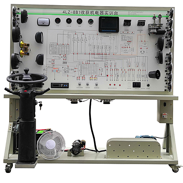
ZOPNJ-40 harvesting machine full vehicle electrical appliance training and training platform
The harvester‘s full vehicle electrical appliances, corn harvesting vehicle electrical training platform starting system and charging system and other electrical appliances composition structure and working process. It can meet the teaching needs of the theory and maintenance training of vehicle electrical appliances during the training of harvesting machines.
Objective: Based on the actual electrical appliances of the 4LZ-8B1 harvester vehicle, it can fully demonstrate the composition and working process of each electrical system such as the instrument system, lighting system, wiper system, horn system, starting system and charging system. It can meet the teaching needs of vehicle electrical theory and m*ntenance tr*ning during harvester tr*ning.
Function
1. Real and operational vehicle electrical system, fully demonstrating the composition and structure of the vehicle electrical system.
After turning on the power, you can operate various electrical switches, buttons, instrument systems, lighting systems, wiper systems, horn systems, starting systems, charging systems and other electrical systems on the teaching board to truly demonstrate their working processes.
2. The equipment panel must be impact-resistant, pollution-resistant, fire-proof, and moisture-proof, and the surface must be sprayed with primer; a color circuit diagram that will never fade must be printed on the panel.
3. Detection terminals are installed on the panel, which can directly detect the electrical signals of circuit components of each vehicle electrical system on the panel, such as resistance, voltage, current, frequency signals, etc.
4. Mechanical assembly and fitter assembly virtual simulation software: This software is developed based on unity3d, with optional 6-level image quality. It is equipped with the design and virtual disassembly and assembly of reducers and shafting structures, the design and simulation of common mechanical mechanisms , and a mechanism resource library. For a typical mechanical mechanism (virtual disassembly and assembly of a gasoline engine), the software is a whole software and cannot be individual resources.
A. Reducer design and virtual disassembly interface can choose worm gear bevel gear reducer, two-stage expanded cylindrical gear reducer, bevel cylindrical gear reducer, coaxial cylindrical gear reducer, bevel gear reducer, and one-stage cylindrical gear reducer. Gear reducer.
Worm bevel gear reducer: After entering the software, the assembly content is automatically played. Each step in the video has a text description
. Secondary expandable cylindrical gear reducer: After entering the software, the content is played in the form of a video. The video content should include: Part name ( Scan the QR code to see the names of parts), disassembly and assembly demonstration (including disassembly and assembly), virtual disassembly (including overall, low-speed shaft, medium-speed shaft, high-speed shaft, box cover, box seat)
conical cylindrical gear reducer, Coaxial cylindrical gear reducer, bevel gear reducer, first-level cylindrical gear reducer: click to enter and automatically jump to the edrawings interface. The models are all three-dimensional models . By clicking on the parts, the names of the parts are displayed, and the 360° view is av*lable Rotate, enlarge, reduce, translate, and at the same time, the entire reducer can be disassembled and assembled through the moving parts function. At the same time, you can select the home button to return to the original state of the reducer. The bevel gear reducer and first-stage cylindrical gear reducer have added the function of inserting a cross section, and the cross section can be freely dragged to observe the internal structure of the reducer.
B. Shaft structure design and virtual disassembly and assembly interface optional parts recognition, disassembly and assembly demonstration, and actual operation. 1. Parts recognition: three-dimensional model and part name
including helical gear, non-hole end cover, coupling, coupling key, shaft, gear key, hole end cover, shaft sleeve, deep groove ball bearing, any All parts can be rotated 360° 2. Disassembly and assembly demonstration: There are 2 built-in cases. When you move the mouse to the position of a cert*n part (except the base and bearing seat), the part will automatically enlarge and the name of the part will be displayed. It is equipped with disassembly and Assembly button, the function is to automatically complete the disassembly and assembly of the shaft system structure by the software. All three-dimensional scenes can be rotated, enlarged, reduced and translated 360° in all directions. 3. Practical operation: The three-dimensional parts are neatly placed on the table. The students manually select the corresponding parts and move them to the shaft system structure. The parts can be installed only when they are placed in the correct order and in the correct position. There is a restart button to facilitate students to restart. Conduct virtual experiments. When you move the mouse to a cert*n part position (except the base and bearing seat), the part will automatically enlarge and the part name will be displayed. C. Common mechanical mechanism design and simulation, optional hinge four-bar mechanism design and analysis, I\II type crank rocker mechanism design and analysis, offset crank slider mechanism design and analysis, crank swing guide rod mechanism design and analysis, hinge Four-bar mechanism with integrated trajectory, eccentric linear-acting roller push rod cam , and centering linear-acting flat-bottomed push rod cam . 1. Each mechanism should be able to input corresponding parameters, and the software can automatically calculate the parameters, and can perform motion simulation and automatically draw curves. D. The mechanism resource library includes 11 types of planar link mechanisms, 5 types of cam mechanisms, 6 types of gear mechanisms, 8 types of transmission mechanisms, 11 types of tightening mechanisms, 6 types of gear tr*n mechanisms, and 8 types of other mechanisms ( mechanical equipment simulation) E , virtual disassembly and assembly of gasoline engines, optional crankcase assembly and disassembly demonstration, crankcase virtual assembly, valve tr*n assembly and disassembly demonstration, valve tr*n virtual assembly 1, crankcase assembly and disassembly demonstration and valve tr*n assembly and disassembly demonstration both have disassembly button, assembly button, restart, and decomposition observation button. When the mouse is moved to a cert*n part position, the part will automatically enlarge and the part name will be displayed. The software automatically completes the disassembly and assembly of the shaft system structure. When using the decomposition observation button, the 3D model of the crankcase or gas distribution system automatically displays an exploded view, which can be rotated, enlarged, reduced, and translated 360°. 2. The 3D parts of the crankcase virtual assembly and the gas distribution system virtual assembly are neatly arranged When placed on the desktop, students manually select the corresponding parts and move them to the mechanism. The parts can be installed only when they are placed in the correct order and in the correct position. There is a restart button to facilitate students to re-perform the virtual experiment. When you move the mouse to cert*n part locations, the part names are automatically displayed. 5. Technical specifications Power supply: three-phase four-wire (or three-phase five-wire) 380V±10% 50Hz Working voltage: DC 24V Working temperature: room temperature Three-phase asynchronous motor Appearance: 1740*650*1700mm 6. Basic configuration
| serial number | name | Specifications and models | unit | quantity |
| 1 | panel | Equipped with various detection terminals and color circuit diagrams | set | 1 |
| 2 | Ignition Switch | Original car | indivual | 1 |
| 3 | instrument cluster | Original car | set | 1 |
| 4 | Combination Switch | Original car | set | 1 |
| 5 | Left and right headlight assemblies | Original car | set | 1 |
| 6 | working lamp | Original car | set | 1 |
| 7 | Left and right turn signals | Original car | set | 1 |
| 8 | Left and right turn side lights | Original car | set | 1 |
| 9 | Left and right combination t*l lights | Original car | set | 1 |
| 10 | light switch | Original car | set | 1 |
| 11 | brake light switch | Original car | set | 1 |
| 12 | Reversing light switch | Original car | set | 1 |
| 13 | hazard light switch | Original car | set | 1 |
| 14 | Wiring harness | / | set | 1 |
| 15 | Wiper assembly | Original car | set | 1 |
| 16 | Wiper control relay | Original car | indivual | 1 |
| 17 | trumpet | Original car | indivual | 2 |
| 18 | Horn relay | Original car | indivual | 1 |
| 19 | Starter assembly | Original car | tower | 1 |
| 20 | Generator assembly | Original car | tower | 1 |
| twenty one | Three-phase asynchronous motor | / | tower | 1 |
| twenty two | battery | / | tower | 1 |
| twenty three | Fuse box | / | indivual | 1 |
| twenty four | m*n power switch | 50A | indivual | 1 |
| 26 | Fault simulation and troubleshooting device | / | set | 1 |
| 27 | Equipment Manual | / | set | 1 |
| 28 | Certificate and warranty card | / | set | 1 |
| 29 | imaging system | Original car | set | 1 |
| 30 | sound system | Original car | set | 1 |
| 31 | electronic fan | Original car | set | 1 |
- Previous:ZOPNJ-23 Tractor Anti-Latual Training Platform
- Next:ZOPGC-04 Twita Twita Machine Starting and Charging System Training Platform
Recommended Products