Product
News
- Excavator steering system anatomy training desk
- Hydraulic front hanging mechanical experimental device
- Water pump performance experimental device
- Contact oxidation pool training desk
- Drinking water treatment process training desk
- Reverse osmosis membrane training
- Softness and salt removal experimental device
- Salvation tank experimental device
- Aerobic biological treatment training device
- Bio -turntable principle experimental device
- Lucky ratio blocking test device
- Socci condiment training desk
- Industrial wastewater treatment training desk
- Industrial wastewater treatment process simulation experimental device
- CNC milling machine installation and maintenance training table
- CNC Machining Center Maintenance and Processing Technical Experimental Desk
- AC Voltage Merragatory System Electrical Experiment Device
- Solar power generation experimental device
- Electrical experimental device of ship anchor machine
- Worker Electrical Engineering Technology Training Device
Contact us
WeChat:15372285263
Phone:15372285263
WhatsApp:15372285263
Address:Building 3, No. 7 Longyuan Road, Shuige Industrial Park, Liandu District, Lishui City, Zhejiang Province
Mechanical Basic
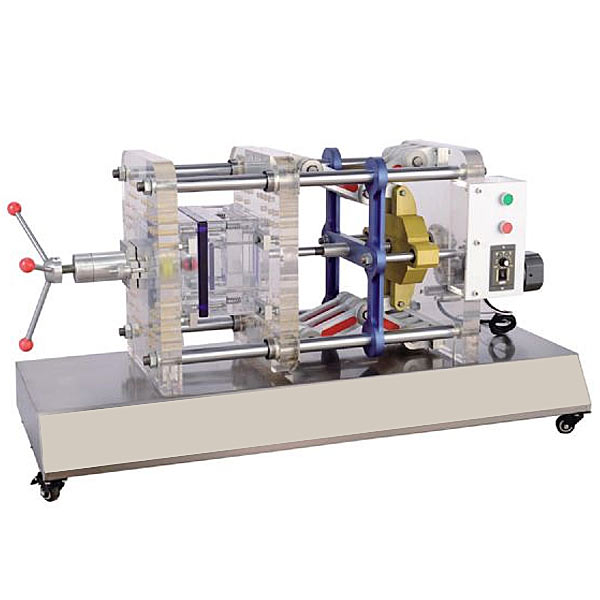
ZOP-S2 visual injection molding simulation training device
Visual injection molding molding machine, transparent injection molding machine simulation experimental device does not need to add any raw materials, you can perform the structural principle demonstration experiment of the injection molding machine. The operation is simple, intuitive and easy to understand, and improves fun.
1. Overview:
This machine is a miniaturized and improved production machine. It is small and can be moved at will. It is suitable for classroom teaching and provides mold design and manufacturing personnel with a certified mold movement and forming analysis micro experimental bench . The product includes mold opening, mold closing mechanism, ejection mechanism, body, control system and feeding device. It has a simple structure, easy operation, no pollution when playing, and can use 220V voltage. It can be used in any electric field, subject to the restrictions of industrial electricity; it fills
the gap of no experimental machine in mold teaching. The movement process of the mold can be seen in the experiment, thereby transforming rationality into perceptual knowledge.
This set of injection molding simulator does not require the addition of any raw materials, and can be used to demonstrate the structural principles of the injection molding machine. The operation is simple, intuitive and easy to understand, making it more interesting. It is safe and reliable for students to operate. It is a good teaching equipment in basic mold teaching .
2. Technical parameters:
1. AC power supply: single-phase 220VAC 50HZ
2. Supporting mold size: 240x150mm
3. Demonstration table size (mm): 1200x500x600
4. Machine weight: about 70kg
3. Supporting injection mold: (optional)
4. Microcontroller and PLC programmable design and control virtual simulation software.
This software is developed based on unity3d. It has built-in task books and experimental prompts. It adopts the form of three-dimensional roaming. Movement can be controlled by the keyboard, the direction of the lens can be controlled by the mouse, and the distance of the picture can be controlled by the mouse wheel. Rotated 360 degrees, the three-dimensional wall has electrical diagrams p*nted on it.
1. Equipment component assembly: Follow the highlighted prompts to find the component control rack. You can drag components from the component library according to the electrical component layout diagram and place them on the component control rack. The component library is equipped with control panels, switching power supplies, micro relays, and PLCs. , frequency converter, stepper motor , AC motor, servo motor, servo driver, stepper driver, interface board, operation panel, circuit breaker, servo motor interface, digital display voltmeter, there will be a prompt when the selection is wrong.
2. Technical indicator measurement: Select a multimeter to check the servo motor connection cable and the servo driver with BOP panel. Adjust the left and right buttons to the ohm range, drag the black and red test leads and insert them into the R, S, T, U, V, W, and ground phases respectively for testing. For resistance value, according to the highlighted prompt, find the power switch in the scene, drag the pen or multimeter to measure whether the power is on.
3) Connection of electrical components: According to the electrical wiring diagram, connect the power lines and control lines, highlight the interface, connect the driver, interface board, power line, servo motor, encoder, PLC, and relay in order, and turn on the m*n power After switching on the switch, servo power switch, and faulty circuit switch, a fault code will be prompted and you can select the cause of the fault from three items.
4) Parameter adjustment test: Turn on the power to adjust the speed, set the driver parameters according to the requirements of the mission statement, perform inching control/analog speed adjustment/multi-stage speed control, and observe the three-dimensional servo motor motion control. Select any of the 6 PLC programs and then adjust the servo drive analog speed. The PLC parameters are adjustable. Set the drive parameters and enter the three-dimensional servo motor motion control interface and electrical display interface. The operation panel is equipped with servo start, low speed, medium Speed, high speed, servo stop, torque limit, abnormal reset, forward/reverse rotation selection, 0-10 sliding control (the electrical panel displays the value in real time).
5) Inspect the three-dimensional virtual simulation machine of the servo system mask machine, observe its structure, inject fault points, select multiple fault causes, and locate faults. Connect the fault causes with the corresponding detection and positioning methods, and troubleshoot after selecting the correct ones. Connect the cause of the f*lure with the corresponding solution.
6) Control process plan, optional single machine mode and online mode of inching control/analog speed regulation/multi-stage speed regulation control, call up the control panel, display the operation of 3 production lines, perform real-time control, optional inching, low and medium High-speed, start and stop control, the speed is adjustable. According to the control plan, the system automatically determines the performance of the production line and submits a disclosure record.
This machine is a miniaturized and improved production machine. It is small and can be moved at will. It is suitable for classroom teaching and provides mold design and manufacturing personnel with a certified mold movement and forming analysis micro experimental bench . The product includes mold opening, mold closing mechanism, ejection mechanism, body, control system and feeding device. It has a simple structure, easy operation, no pollution when playing, and can use 220V voltage. It can be used in any electric field, subject to the restrictions of industrial electricity; it fills
the gap of no experimental machine in mold teaching. The movement process of the mold can be seen in the experiment, thereby transforming rationality into perceptual knowledge.
This set of injection molding simulator does not require the addition of any raw materials, and can be used to demonstrate the structural principles of the injection molding machine. The operation is simple, intuitive and easy to understand, making it more interesting. It is safe and reliable for students to operate. It is a good teaching equipment in basic mold teaching .
2. Technical parameters:
1. AC power supply: single-phase 220VAC 50HZ
2. Supporting mold size: 240x150mm
3. Demonstration table size (mm): 1200x500x600
4. Machine weight: about 70kg
3. Supporting injection mold: (optional)
| serial number | product name | Model specifications (mm) | serial number | product name | Model specifications (mm) |
| 1 | Single parting surface mold | 240×150 | 7 | Incline guide column mold | 240×150 |
| 2 | Double parting surface mold | 240×150 | 8 | Haf model | 240×150 |
| 3 | Submersible gate mold | 240×150 | 9 | Inclined top mold | 240×150 |
| 4 | Reset the mold first after ejection | 240×150 | 10 | Rotating tooth pattern mold | 240×150 |
| 5 | Push plate mold | 240×150 | 11 | Hot runner mold | 240×150 |
| 6 | Second ejection mold | 240×150 | 12 | Bend pipe mold | 240×150 |
This software is developed based on unity3d. It has built-in task books and experimental prompts. It adopts the form of three-dimensional roaming. Movement can be controlled by the keyboard, the direction of the lens can be controlled by the mouse, and the distance of the picture can be controlled by the mouse wheel. Rotated 360 degrees, the three-dimensional wall has electrical diagrams p*nted on it.
1. Equipment component assembly: Follow the highlighted prompts to find the component control rack. You can drag components from the component library according to the electrical component layout diagram and place them on the component control rack. The component library is equipped with control panels, switching power supplies, micro relays, and PLCs. , frequency converter, stepper motor , AC motor, servo motor, servo driver, stepper driver, interface board, operation panel, circuit breaker, servo motor interface, digital display voltmeter, there will be a prompt when the selection is wrong.
2. Technical indicator measurement: Select a multimeter to check the servo motor connection cable and the servo driver with BOP panel. Adjust the left and right buttons to the ohm range, drag the black and red test leads and insert them into the R, S, T, U, V, W, and ground phases respectively for testing. For resistance value, according to the highlighted prompt, find the power switch in the scene, drag the pen or multimeter to measure whether the power is on.
3) Connection of electrical components: According to the electrical wiring diagram, connect the power lines and control lines, highlight the interface, connect the driver, interface board, power line, servo motor, encoder, PLC, and relay in order, and turn on the m*n power After switching on the switch, servo power switch, and faulty circuit switch, a fault code will be prompted and you can select the cause of the fault from three items.
4) Parameter adjustment test: Turn on the power to adjust the speed, set the driver parameters according to the requirements of the mission statement, perform inching control/analog speed adjustment/multi-stage speed control, and observe the three-dimensional servo motor motion control. Select any of the 6 PLC programs and then adjust the servo drive analog speed. The PLC parameters are adjustable. Set the drive parameters and enter the three-dimensional servo motor motion control interface and electrical display interface. The operation panel is equipped with servo start, low speed, medium Speed, high speed, servo stop, torque limit, abnormal reset, forward/reverse rotation selection, 0-10 sliding control (the electrical panel displays the value in real time).
5) Inspect the three-dimensional virtual simulation machine of the servo system mask machine, observe its structure, inject fault points, select multiple fault causes, and locate faults. Connect the fault causes with the corresponding detection and positioning methods, and troubleshoot after selecting the correct ones. Connect the cause of the f*lure with the corresponding solution.
6) Control process plan, optional single machine mode and online mode of inching control/analog speed regulation/multi-stage speed regulation control, call up the control panel, display the operation of 3 production lines, perform real-time control, optional inching, low and medium High-speed, start and stop control, the speed is adjustable. According to the control plan, the system automatically determines the performance of the production line and submits a disclosure record.
- Previous:ZOP-S3 transparent stamping simulation training device
- Next:ZOP-S1 transparent hydraulic injection machine demonstration training device
Recommended Products