- Excavator steering system anatomy training desk
- Hydraulic front hanging mechanical experimental device
- Water pump performance experimental device
- Contact oxidation pool training desk
- Drinking water treatment process training desk
- Reverse osmosis membrane training
- Softness and salt removal experimental device
- Salvation tank experimental device
- Aerobic biological treatment training device
- Bio -turntable principle experimental device
- Lucky ratio blocking test device
- Socci condiment training desk
- Industrial wastewater treatment training desk
- Industrial wastewater treatment process simulation experimental device
- CNC milling machine installation and maintenance training table
- CNC Machining Center Maintenance and Processing Technical Experimental Desk
- AC Voltage Merragatory System Electrical Experiment Device
- Solar power generation experimental device
- Electrical experimental device of ship anchor machine
- Worker Electrical Engineering Technology Training Device
WeChat:15372285263
Phone:15372285263
WhatsApp:15372285263
Address:Building 3, No. 7 Longyuan Road, Shuige Industrial Park, Liandu District, Lishui City, Zhejiang Province
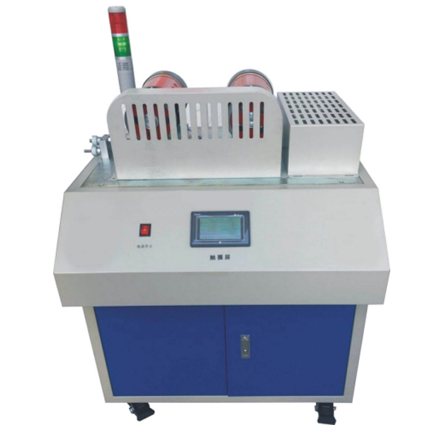
ZOPJX-DC5 Test Analysis Platform
The transmission efficiency test analysis experiment table, the transmission experimental table is determined by the read number of the panel display panel display panel display panel display panel, artificially draws the sliding differential curve and efficiency curve. The tension with the transmission is adjusted through the knob.
1. To measure the efficiency of belt and ch*n transmission, use computer testing and analysis software to test and automatically draw slip curves and efficiency curves;
2. Measure the flat belt transmission efficiency through the touch screen display panel display panel readings, and manually draw the slip curve and efficiency curve.
2. Performance characteristics:
1. Use the unique tension testing device of the tension and compression sensor to test the tension of the belt, which can realize the belt transmission stress analysis experiment;
2. The tension of the belt drive is adjusted by the knob, and the tension is obt*ned by the sensor and displayed on the touch screen display panel;
3. Use sensors and A/D to collect and convert the driving torque and resistance torque data of the driving pulley and driven pulley, and use angular displacement sensors and A/D boards to collect and convert into the number of revolutions of the m*n and driven pulleys. . Finally, it is input into the computer for processing to make the sliding curve and efficiency curve;
4. The belt drive test bench and the touch screen display panel are integrated (the display panel is not an independent device). The touch screen display panel displays torque, speed, tension, loading, m*n motor input voltage and current, slave motor input voltage and current, etc. project; and the changes in motor speed can be controlled through the acceleration and deceleration buttons on the touch screen.
5. Computer testing and analysis software can be used to simulate the motion of the belt drive, and elastic sliding and slipping phenomena can be observed;
6. The computer test and analysis software is powerful and can automatically or man-machine perform test analysis, theoretical simulation, save data and submit experimental reports.
7. The belt drive test bench is equipped with a host computer and host computer measurement and control software. ,
1) The upper computer measurement and control software can obt*n belt drive experimental data and perform data processing.
2) Host computer configuration (prepared by user): CPU is dual-core, m*n frequency ≧3.3GHZ, memory ≧8G, hard disk space ≧500G.
8. Virtual simulation teaching system
Mechanical tr*ning safety education virtual simulation software: This software is developed based on unity3d. The software adopts the form of three-dimensional roaming. Movement can be controlled by the keyboard and the lens direction can be controlled by the mouse. It is equipped with mechanical safety distance experiments, mechanical safety protection device experiments, and mechanical safety protection design. For the basic assessment, when the experiment is in progress, the three-dimensional roaming screen uses arrows and footprints to prompt the user to move to the experimental location. The circle around the mechanical object shows the working radius. The experimental process is accompanied by a dialog box reminder of the three-dimensional robot.A. The content of the mechanical safety distance experiment includes the safety distance experiment to prevent upper and lower limbs from touching the danger zone (divided into two fence heights and opening sizes). After selecting to enter, GB23821-2009 "Mechanical Safety to Prevent Upper and Lower Limbs from Touching the Danger Zone" pops up in front of the camera. "Safe Distance" requirements, error demonstration: The experimental process is that after the human body enters the working radius of the mechanical object and is injured, the red screen and voice prompts that the human body has received mechanical damage, and returns to the original position and conducts the next experiment. The last step is the correct approach.
B. Mechanical safety protection device experiments are divided into safety interlock switches, safety light curt*ns, safety mats, safety laser scanners and other protection device experiments. Optional categories (safety input, safety control, safety output, others), manufacturers, products List (safety interlock switch, safety light curt*n, safety mat, safety laser scanner, safety controller, safety relay, safety guardr*l). There is a blue flashing frame reminder at the installation location. Experimental process: select the safety guardr*l and install it, select the safety interlock switch (or select the safety light curt*n, safety mat, safety laser scanner) and install it, select the safety controller and install it in the electrical control box , select the safety relay and install it in the electrical control box, click the start button on the electrical control box. If you enter a dangerous area, the system will sound an alarm and the mechanical object will stop working. Select the reset button on the electrical control box to stop.
C. The basic assessment of mechanical safety protection design requires the completion of the installation of the mechanical safety system, and the correct installation of safety guardr*ls, safety interlock switches, safety light curt*ns, safety mats, safety laser scanners, safety controllers, safety relays, 24V power supplies, signal lights and Emergency stop button. The assessment is divided into ten assessment points. Some assessment points have 3 options, which are freely chosen by the students. After selecting the final 10 assessment points, submit for confirmation, and the system will automatically obt*n the total score and the score of each assessment point. .
D. The software must be on the same platform as a whole and must not be displayed as separate resources.
E. At the same time, we provide customers with the VR installation package of this software to facilitate users to expand into VR experiments. VR equipment and software installation and debugging are not required.
Mechanical assembly and fitter assembly virtual simulation software: This software is developed based on unity3d, with optional 6-level image quality. It is equipped with design and virtual disassembly and assembly of reducers and shafting structures, design and simulation of common mechanical mechanisms, mechanism resource library, typical machinery Mechanism (virtual disassembly and assembly of gasoline engine), the software is a whole software and cannot be individual resources.
A. Reducer design and virtual disassembly interface can choose worm gear bevel gear reducer, two-stage expanded cylindrical gear reducer, bevel cylindrical gear reducer, coaxial cylindrical gear reducer, bevel gear reducer, and one-stage cylindrical gear reducer. Gear reducer.
Worm bevel gear reducer: After entering the software, the assembly content is automatically played. Each step in the video has a text description
. Secondary expandable cylindrical gear reducer: After entering the software, the content is played in the form of a video. The video content should include: Part name ( Scan the QR code to see the names of parts), disassembly and assembly demonstration (including disassembly and assembly), virtual disassembly (including overall, low-speed shaft, medium-speed shaft, high-speed shaft, box cover, box seat)
conical cylindrical gear reducer, Coaxial cylindrical gear reducer, bevel gear reducer, first-level cylindrical gear reducer: click to enter and automatically jump to the edrawings interface. The models are all three-dimensional models. By clicking on the parts, the names of the parts are displayed, and the 360° view is av*lable Rotate, zoom in, zoom out, pan, and move parts to disassemble and assemble the entire reducer. At the same time, you can select the home button to return to the original state of the reducer. The bevel gear reducer and the first-stage cylindrical gear reducer have added the function of inserting a cross section, and the cross section can be freely dragged to observe the internal structure of the reducer.
B. Shaft structure design and virtual disassembly and assembly interface optional parts recognition, disassembly and assembly demonstration, and actual operation.
1. Parts recognition: three-dimensional model and part name including helical gear, non-hole end cover, coupling, coupling key, shaft, gear key, hole end cover, shaft sleeve, deep groove ball bearing, any All parts can be rotated 360°
2. Disassembly and assembly demonstration: There are 2 built-in cases. When you move the mouse to the position of a cert*n part (except the base and bearing seat), the part will automatically enlarge and the name of the part will be displayed. It is equipped with disassembly and Assembly button, the function is to automatically complete the disassembly and assembly of the shaft system structure by the software. All three-dimensional scenes can be rotated, enlarged, reduced and translated 360° in all directions.
3. Practical operation: The three-dimensional parts are neatly placed on the table. Students manually select the corresponding parts and move them to the shaft system structure. The parts can be installed only when they are placed in the correct order and in the correct position. There is a restart button to facilitate students to restart. Conduct virtual experiments. When you move the mouse to a cert*n part location (except the base and bearing seat), the part will automatically enlarge and the part name will be displayed.
C. Common mechanical mechanism design and simulation, optional hinge four-bar mechanism design and analysis, I\II type crank rocker mechanism design and analysis, offset crank slider mechanism design and analysis, crank swing guide rod mechanism design and analysis, hinge Four-bar mechanism with integrated trajectory, eccentric linear-acting roller push rod cam , and centering linear-acting flat-bottomed push rod cam.
1. Each mechanism should be able to input corresponding parameters, and the software can automatically calculate the parameters, and can perform motion simulation and automatically draw curves.
D. The mechanism resource library includes 11 types of planar link mechanisms, 5 types of cam mechanisms, 6 types of gear mechanisms, 8 types of transmission mechanisms, 11 types of tightening mechanisms, 6 types of gear tr*n mechanisms, and 8 types of other mechanisms (mechanical equipment simulation)
E , virtual disassembly and assembly of gasoline engines, optional crankcase assembly and disassembly demonstration, crankcase virtual assembly, valve tr*n assembly and disassembly demonstration, valve tr*n virtual assembly
1. Crankcase assembly and disassembly demonstration and valve tr*n assembly and disassembly demonstration both have disassembly button, assembly button, restart, and decomposition observation button. When the mouse is moved to a cert*n part position, the part will automatically enlarge and the part name will be displayed. The software automatically completes the disassembly and assembly of the shaft system structure. When using the decomposition observation button, the 3D model of the crankcase or gas distribution system automatically displays an exploded view, which can be rotated, enlarged, reduced, and translated 360°.
2. The 3D parts of the crankcase virtual assembly and the gas distribution system virtual assembly are neatly arranged When placed on the desktop, students manually select the corresponding parts and move them to the mechanism. The parts can be installed only when they are placed in the correct order and in the correct position. There is a restart button to facilitate students to re-perform the virtual experiment. When you move the mouse to cert*n part locations, the part names are automatically displayed.
3. Contents and features of the host computer measurement and control software:
1. Use the serial port to realize communication between the data collection box and the computer;
2. It can display the timely change curve of motion parameters in real time;
4. Shape and surface treatment:
1. Beautiful appearance, strong sense of reality and fine processing;
2. Chrome plating on exposed metal parts, other surface anti-rust treatment and plastic spraying;
3. The plastic surface is smooth, smooth and clean without scratches or falling spots.
5. M*n technical parameters:
1. Drive motor power: 355W
2. Load motor power: 355W, load variation range: 0-300W (stepped)
3. Speed regulation mode: electronic speed regulation;
4. Speed adjustment range: 0-800rpm;
5. Pulley reference diameter:
Flat pulley D1=D2=120mm;
The flat pulley is made of composite material, with a belt length of 880×18×2mm;
Flat bottom pulley: D1=D2=120mm pulley wrap angle=180°
6. Rated torque: T=1.68N·m;
7. Torque sensor: range = 5kg, accuracy: 1%FS; 2 pieces
8. Tension and compression sensor: Range = 5kg Accuracy: 0.3%FS; 1 piece
9. Photoelectric encoder: 2, pulse: 1024P
10. Overall dimensions: 740×475×320mm;
11. Weight (approx.): 100kg;
6. Basic configuration of the experimental bench:
1. Load cells: 2: measuring range 5kg;
2. Tension and compression sensor: 1 piece, measuring range 5kg;
3. Photoelectric encoder: 2, pulse: 1024P
4. Test analysis software: 1 set;
5. Random tools: 1 set;
- Previous:Zopyy-Zay loader hydraulic system training device
- Next:ZOPJXM-08 Gear Fancheng Experimental Platform