Product
News
- Excavator steering system anatomy training desk
- Hydraulic front hanging mechanical experimental device
- Water pump performance experimental device
- Contact oxidation pool training desk
- Drinking water treatment process training desk
- Reverse osmosis membrane training
- Softness and salt removal experimental device
- Salvation tank experimental device
- Aerobic biological treatment training device
- Bio -turntable principle experimental device
- Lucky ratio blocking test device
- Socci condiment training desk
- Industrial wastewater treatment training desk
- Industrial wastewater treatment process simulation experimental device
- CNC milling machine installation and maintenance training table
- CNC Machining Center Maintenance and Processing Technical Experimental Desk
- AC Voltage Merragatory System Electrical Experiment Device
- Solar power generation experimental device
- Electrical experimental device of ship anchor machine
- Worker Electrical Engineering Technology Training Device
Contact us
WeChat:15372285263
Phone:15372285263
WhatsApp:15372285263
Address:Building 3, No. 7 Longyuan Road, Shuige Industrial Park, Liandu District, Lishui City, Zhejiang Province
Mechanical Basic
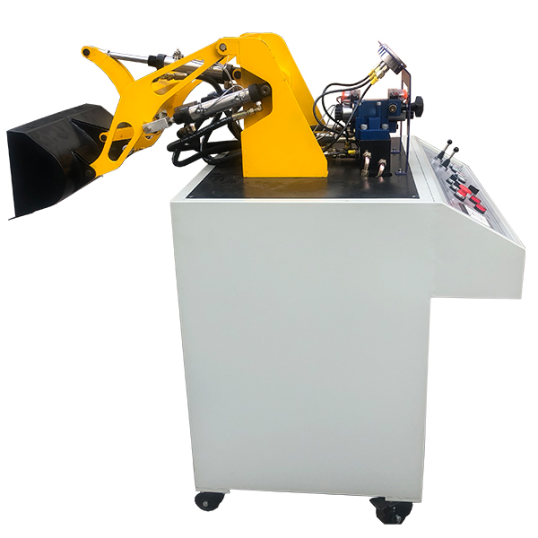
Zopyy-Zay loader hydraulic system training device
The training device of the loader hydraulic system, the training platform of the loader hydraulic system is reduced by the all -metal structure that reduces the physical proportion. The hydraulic system is activated during the experiment to operate the machine according to the experimental requirements.
Hydraulic loaders are the m*n machinery in mechanical engineering. They are widely used in earthwork construction and mining loading operations such as engineering construction , road construction, hydraulic engineering, and national defense fortifications. As a mobile machine, loaders are widely used in earthmoving, loading, lifting and transporting stones, loose goods and piles of goods. Loaders also have light shoveling capabilities. In recent years, the application of high-tech microelectronics technology in hydraulic technology has made the comprehensive technical level of engineering machinery and construction machinery higher and higher, improving the reliability, operational safety, comfort and service life of these machinery, and making its adaptability better. powerful.
1. Experimental items
1. Observation of the structure and working principle of each component of the hydraulic transmission, and disassembly and assembly experiments.
2. Hydraulic loading machinery demonstration control experiment.
3. PLC software simulation demonstration and control experiment.
4. Programmable controller (PLC) electrical control experiment: mechanical-electrical-hydraulic integrated control experiment.
2. Experiment content
1. Hydraulic loading machinery demonstration control experiment
1) Loading operation, the rocker arm cylinder extends after the bucket is loaded, causing the bucket to reverse and the boom lifts;
2) Unloading operation, the bucket unloads ( The rocker arm retracts, causing the bucket to turn) and the boom lowers.
2. Programmable controller (PLC) electrical control experiment: mechanical-electrical-hydraulic integrated control experiment.
1) Learning PLC instruction programming and ladder diagram programming;
2) Learning and using PLC programming software;
3) Communication and online debugging between PLC and computer;
4) Application of PLC in hydraulic transmission control and optimization of control schemes.
3. Performance and Characteristics
1. The experimental bench is made of cold-rolled steel plates (and has undergone plastic spraying and anti-corrosion treatment). It has a desktop structure and integrated control and operation.
2. The electrical operation control is bottom-mounted, and the hydraulic station is placed in the m*n cabinet of the hydraulic table. The overall structure is compact and coordinated, the layout is beautiful and generous, and it is highly practical and can be used for experiments by 4-6 people.
3. The loading machine has an all-metal structure scaled down to the actual scale. During the experiment, the hydraulic system is activated to operate the machine according to the experimental requirements.
4. The loading machinery is made according to the structure and reduced scale of the real thing, which can truly reflect the actual working conditions of the machinery, allowing students to deeply understand the structure and working principle of each component of the mechanism during the experiment.
5. Experimental control adopts two methods: manual control and automatic control.
6. The experimental components adopt pressure-resistant hoses, and the pressure can reach 25Mpa.
7. With three-phase leakage protection, the output voltage is 380V/220V. If the leakage current to the ground exceeds 30mA, the power supply will be cut off. The electrical control adopts DC 24V power supply and has overvoltage protection to prevent damage to the equipment due to misoperation.
8. Hydraulic and pneumatic transmission design and control virtual simulation software: This software is developed based on unity3d. The software adopts the form of three-dimensional roaming. Movement can be controlled by the keyboard and the lens direction can be controlled by the mouse. The interface is equipped with home page, help, full screen, component recognition, and loop. Construction, key component testing, typical system testing interface.
1. Component identification adopts the form of automatic playback, which introduces the m*lbox, liquid level gauge, oil pump unit on the equipment (the pop-up hydraulic symbols, principles and introduction are introduced here, click OK to enter the next introduction), valve frame, and pressure gauge. , sensors , etc.
2. The disassembly and assembly of components is divided into learning mode and assessment mode. There are built-in electromagnetic reversing valves, plate relief valves, plunger pumps, filter valves, and electro-hydraulic servo valves. In the learning mode, the disassembly sequence is prompted and highlighted. There are no prompts for disassembly and installation in assessment mode. If the disassembly and assembly sequence is wrong, the next step of disassembly and assembly will no longer be possible. The toolbar is equipped with draggable seals, pumps, valves, oil filters, hex wrenches, pipe wrenches, adjustable wrenches, dead wrenches, and M5 screws.
3. The hydraulic components are equipped with one-way valve (hydraulic control, poppet valve core, ball valve core), m*n structure of the reversing valve (O type, Y type, H type), hydraulic cylinder (assembled plunger, double-acting single outlet rod) , double-action double-output rod, single-action double-output rod, single-action single-output rod), etc. Each construction experiment adopts a graphical method and is constructed by dragging the set graphics. In the graphics library There are confusing graphics.
4. Hydraulic selection is based on the hydraulic schematic diagram, and then selects the nominal displacement of the pump (12 items, including 11 confusing items) and pressure level (5 items, including 4 confusing items), and the selection of the solenoid relief valve (3 specifications, 3 pressure levels, and 3 flow levels, all of which have confusing items), oil filter selection (multiple choices include confusing items), servo valve selection (multiple choices include confusing items), and the wrong selection system will Automatically prompt the correct answer. After selecting, drag the corresponding tool to the highlighted area according to the prompt.
5. Circuit inspection is done by selecting the correct accessories, including the selection of sealing rings, checking valve switches, etc. Then proceed to the next step to turn on the machine. Follow the prompts to turn on the machine. After turning on the machine, enter the monitoring interface. Turn on the equipment one by one according to the prompts. The prompts are in the form of text and button highlighting.
6. Hydraulic cylinder pressure test Enter the experiment through the test button on the background interface and gradually analyze To start friction test, start friction force, parameter setting, start test, draw curve, stop test.
7. Typical system tests are divided into trial operation, stage response test and frequency response test. The above tests are all conducted through the background monitoring interface.
8. The software must be able to rotate, zoom in and out in all directions to view its det*ls. And the same platform as a whole cannot be displayed as separate resources.
4. M*n technical parameters
Motor model: M3P4H523 Power: 2.2KW Speed: 1420r/min
Oil pump model: V*-15F-A3 Rated pressure: 7Mpa Rated flow: 8ml/rev
Overall dimensions: 1550×650×1800mm
- Previous:ZOPYY-WJY excavator hydraulic system experimental device
- Next:ZOPJX-DC5 Test Analysis Platform
Recommended Products