Product
News
- Excavator steering system anatomy training desk
- Hydraulic front hanging mechanical experimental device
- Water pump performance experimental device
- Contact oxidation pool training desk
- Drinking water treatment process training desk
- Reverse osmosis membrane training
- Softness and salt removal experimental device
- Salvation tank experimental device
- Aerobic biological treatment training device
- Bio -turntable principle experimental device
- Lucky ratio blocking test device
- Socci condiment training desk
- Industrial wastewater treatment training desk
- Industrial wastewater treatment process simulation experimental device
- CNC milling machine installation and maintenance training table
- CNC Machining Center Maintenance and Processing Technical Experimental Desk
- AC Voltage Merragatory System Electrical Experiment Device
- Solar power generation experimental device
- Electrical experimental device of ship anchor machine
- Worker Electrical Engineering Technology Training Device
Contact us
WeChat:15372285263
Phone:15372285263
WhatsApp:15372285263
Address:Building 3, No. 7 Longyuan Road, Shuige Industrial Park, Liandu District, Lishui City, Zhejiang Province
Electrical training
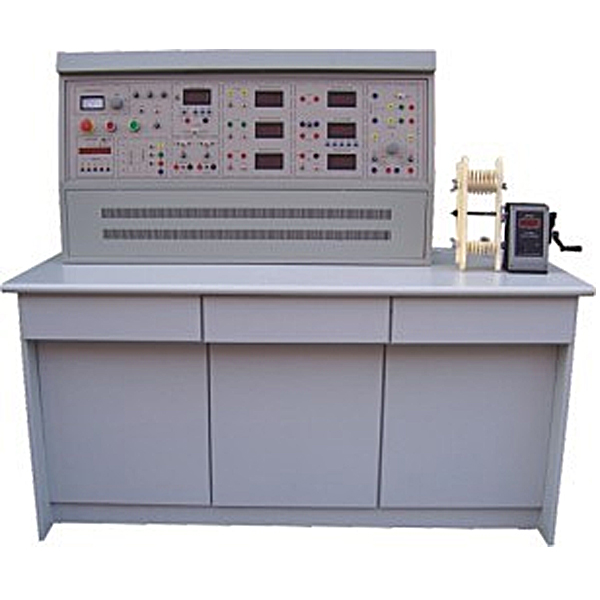
ZOPDJZP-02 Multi-Electrical Architecture Training Device
Multi -motor assembly process training device, DC motor assembly experimental description includes skills in the professional basic knowledge, process preparation, processing and assembly, and testing of motor equipment. It is equipped with the corresponding motor assembly tools and instruments.
ZRDJZP-02 motor assembly skills tr*ning device This device is based on the "National Vocational Qualification Tr*ning Tutorial - Commonly Used Motor Assemblers" (Elementary) compiled by the Ministry of Labor and Social Security and the China Employment Tr*ning Technical Guidance Center. In order to promote commonly used motors A practical tr*ning device developed for the development of assembler vocational tr*ning and vocational skill appr*sal. The content of this tr*ning device includes basic professional knowledge of motor assemblers, process preparation, processing and assembly, inspection work and other skills. It is suitable for teaching and skills tr*ning in related majors offered by higher vocational colleges, junior colleges and secondary vocational colleges. At the same time, the tr*ning device can also be used as an assessment device for skill tr*ning and skill appr*sal in technical schools, vocational education centers, and vocational qualification appr*sal stations (institutes).
1. Device characteristics
1. The practical tr*ning device adopts a modular approach to carry out skill tr*ning.
2. The tr*ning device is equipped with corresponding motor assembly tools and instruments
3. The control panel adopts a solid platform structure, and the measuring instruments are fixed on the control panel.
4. This device has a good self-protection system and provides excellent tr*ning equipment for the realization of an open tr*ning room.
5. It has leakage voltage, leakage current protection devices and instrument over-weighing protection devices, and is safe and in line with national standards.
2. Technical performance
1. Input voltage: three-phase four-wire (or three-phase five-wire) ~ 380V ±10% 50Hz
2. Working environment: The ambient temperature range is -10~+40℃, relative temperature <85% (25℃)
3. Device capacity: <3KVA
4. Weight: 100kg
5. Overall dimensions: 1300mm×750mm×1250mm
3. Equipment and equipment
1. Power control screen
The control panel is made of iron with a double-layer matt dense spray-p*nted structure and an aluminum panel.
2. Tr*ning table
The tr*ning table is made of iron and is equipped with an anti-static insulating rubber pad to protect the operating table.
3. ZP02 m*n control function board equipped with resources
(1) Three-phase four-wire power input, through the leakage protector and m*n switch, is operated by the contactor through the start and stop buttons, and is equipped with an emergency stop control button.
(2) There are three pointer AC voltmeters on the control panel, which are used to monitor the line voltage between each two phases of the three-phase input power supply.
(3) Timer and alarm recorder (service manager), usually used as a clock, with functions such as setting time, timing alarms, cutting off power, etc.; it can also automatically record leakage alarms and instrument overruns caused by wiring or operation errors. The total number of range alarms provides a unified assessment standard for the assessment of students' skill tr*ning.
(4) Three-phase adjustable AC power supply, the voltage is regulated through a 1.5KVA three-phase auto-coupling voltage regulator, and the output is 0~450V/2A.
(5) DC power supply part: 0~30V/2A adjustable DC stabilized power supply, automatic relay shifting, multi-turn potentiometer continuous adjustment, and soft load stop automatic short circuit protection function.
(6) Provide a DC digital voltmeter: measuring range 0~300V, three-and-a-half-digit display, input impedance 10MΩ, accuracy 0.5 level.
(7) A DC digital milliamp meter: measuring range 0~2000mA, three and a half digit display, accuracy level 0.5.
(8) Provide a true effective value AC digital voltmeter with a measuring range of 0 to 500V, an accuracy of 0.5, and a three-and-a-half-digit display.
(9) Three true effective value AC digital ammeters are provided, with a measuring range of 0~5A, an accuracy of 0.5, and a three-and-a-half-digit display.
(10) One screw lamp holder and one double pole double throw switch
(11) Teaching software
1. Electrical safety and electric shock first *d simulation teaching software
The software uses a combination of two-dimensional and three-dimensional virtual images to teach students the safety and first *d methods of using electricity. The software includes single-phase electric shock, two-phase electric shock, step electric shock, low-voltage electric shock first *d, high-voltage electric shock first *d, artificial respiration first *d, Principles of hand-holding breathing rescue method, chest cardiac compression and other protective methods are expl*ned and taught. Principles of single-phase electric shock are divided into rep*ring live disconnection, rep*ring socket electric shock, and outdoor electric shock. The teaching of low-voltage electric shock and high-voltage electric shock m*nly expl*ns and demonstrates to students how to rescue people who are suffering from low-voltage electric shock or high-voltage electric shock. Artificial respiration rescue method, hand-holding breathing rescue method, and chest cardiac compression rescue method are demonstrated using 3D virtual simulation technology. After rendering and Polish it to make the model look like the real part and look realistic. Through practical tr*ning, students can be educated on the safe use of electricity in the tr*ning room, improve students' safety awareness, and enable students to learn some self-rescue methods, so that students can take cert*n safety measures to protect themselves when encountering danger, and become familiar with various Causes of electrical accidents and practical measures to deal with them to reduce the occurrence of electrical accidents.
2. M*ntenance of electricians , electronic motors and vocational qualification tr*ning assessment simulation software
This software is in apk format and can be used on PC or mobile. This software can set faults manually or automatically. This software can manually set fault points through the green box in the circuit diagram (you can set up to 39 fault points), you can also automatically set one random fault point, two random fault points, three random fault points, four random fault points, and five random fault points through the system. It has functions such as toolbox, component library, magnifying glass, circuit diagram, etc. You can choose a multimeter for testing through the toolbox, select appropriate components through the component library, and clearly understand each component and circuit through the magnifying glass. This software allows students to understand the working principle and circuit structure of the motor star-delta start control circuit through the setting of faults in the motor star-delta start control circuit and various investigations.
3. Virtual spectrum analyzer, logic analyzer, oscilloscope, and three-meter simulation software:
This software is in apk format and can be used on PC or mobile terminals. The functions of this software are: resistance measurement, AC voltage measurement (measuring transformer, if the multimeter burns out when measuring the transformer, black smoke will emit prompts and can reset the multimeter), determine the polarity of the transistor, measure the DC voltage (the light turns on when the ammeter is turned on), measure the DC current, and determine the quality of the capacitor. This software can drag the red and black pen tips at will. When the two pen tips are dragged and positioned on the object to be measured, a red circle will be displayed. If the positioning is not accurate, no red circle will be displayed, and when incorrect operations are performed (such as the wrong range selected, If the measured data is wrong, etc.), the meter pointer will be unresponsive, prompting errors and re-measurement, etc. This multimeter can select AC voltage range, DC voltage range, resistance range, current range, resistance adjustment to 0, and can enlarge the display data. Clearly view the measured data size. Students can learn the correct use of multimeters through this software.
4. Microcontroller and plc programmable design and control virtual simulation software:
This software is developed based on unity3d and has built-in experimental steps, experimental instructions, circuit diagrams, component lists, connection lines, power on, circuit diagrams, scene reset, return and other buttons. After the connections and codes are correct, you can start/stop, The forward movement and reverse movement buttons operate the 3D machine tool model to move. In the connected line state, the 3D machine tool model can be enlarged/reduced and translated.
1. Relay control: Read the experiment instructions and enter the experiment. By reading the circuit diagram, select the relays, thermal relays, switches and other components in the component list and drag and drop them into the electrical cabinet. The limiters are placed in the three-dimensional On the machine tool model, you can choose to cover it, and some component names can be renamed. Then click the Connect Line button to connect terminals to terminals. After successfully connecting the machine tool circuit, choose to turn on the power and proceed. If the component or line An error box will pop up if there is a connection error, and the scene can be reset at any time.
2. PLC control: The experiment is the same as relay control, with the addition of PLC control function. After the connection is completed, enter the program writing interface through the PLC coding button, and write two programs, forward and reverse, with a total of 12 ladder diagram symbols. The writing is completed. Finally, select Submit for program verification. After the verification is successful, turn on the power for operation. Error boxes will pop up for component, line connection, and code errors, and the scene can be reset at any time.
3. Single-chip microcomputer control: The experiment is the same as relay control, with the addition of single-chip microcomputer control function. After the connection is completed, enter the programming interface through the C coding button, enter the correct C language code, and after successful submission and verification, turn on the power for operation, components, lines If there are connection or code errors, an error box will pop up, and the scene can be reset at any time.
4. Instruments
(1) A 500V megohmmeter, used to test the insulation resistance of motor windings
(2) 890B+ digital multimeter, three and a half digits display
(3) One clamp ammeter
5. Motors and disassembly and assembly tools, etc.
(1) A set of metalworking tools for disassembly and installation: puller, adjustable wrench, rubber hammer, scribing board, crimping board, elbow scissors, screwdriver, chisel, needle-nose pliers, scraper, feeler gauge, file, soldering iron w*t.
(2) A hand-operated electronic counting winding machine: digital display range 0 ~ 9999 turns, accurate and convenient counting
(3) A set of winding devices: motor winding mold, winding shaft, winding frame, wire crimping frame, etc.
(4) Unp*nted three-phase squirrel cage asynchronous motor: rated power 180W, voltage 380V (Y connection), speed 1400r/min.
(5) Unp*nted separately excited DC motor: rated power 100W, voltage 220V, speed 1500r/min.
(6) Unp*nted synchronous motor: rated power 120W, voltage 380V (Y connection), current 0.35A, speed 1500r/min.
ZRDJZP-02 motor assembly skills tr*ning device
4. Practical tr*ning projects
(1) Assembly of asynchronous motor
1. Embedding and wiring of asynchronous motor windings
① Concentric winding embedded wire
②Ch*n winding embedded wire
③Crossed winding embedded wire
④Short moment double layer winding embedded wire
⑤Double-layer wave winding embedded wire
⑥Double-layer concentric winding embedded wire
2. Insulating impregnation treatment
3. Stator assembly of asynchronous motor
4. Rotor assembly of asynchronous motor
5. General assembly of asynchronous motor
6. Calibration of unit axis
7. Mechanical inspection of motor
8. Winding inspection
①Inspection of winding appearance and geometric dimensions
②Detection of DC resistance
③Three-phase winding current balance test
④Withstand voltage test
(2) Assembly of salient pole synchronous motor
1. Salient pole synchronous motor stator assembly
2. Synchronous motor stator winding embedded wire
3. Salient pole synchronous motor rotor assembly
4. Salient pole synchronous motor rotor winding embedded wire
5. General assembly of salient pole synchronous motor
6. Mechanical inspection of synchronous motors
7. Winding inspection
①Inspection of winding appearance and geometric dimensions
②Three-phase winding current balance test
③Withstand voltage test
(3) DC motor assembly
1. DC motor stator assembly
2. DC motor stator winding embedded wire
3. Armature assembly of DC motor
4. DC motor armature winding embedded wire
5. General assembly of DC motor
6. Mechanical inspection of DC motors
7. Winding inspection
①Inspection of winding appearance and geometric dimensions
②Three-phase winding current balance test
③Withstand voltage test
5. User-equipped instruments and equipment
1. AC withstand voltage tester, short circuit tester
2. Oven, dip tank
Hot-selling products: Hydraulic test bench
- Previous:ZOPGDX-01 Factory Power Supply Technology Training Device
- Next:ZOPDJZP-01 motor assembly skills training device
Recommended Products