- Excavator steering system anatomy training desk
- Hydraulic front hanging mechanical experimental device
- Water pump performance experimental device
- Contact oxidation pool training desk
- Drinking water treatment process training desk
- Reverse osmosis membrane training
- Softness and salt removal experimental device
- Salvation tank experimental device
- Aerobic biological treatment training device
- Bio -turntable principle experimental device
- Lucky ratio blocking test device
- Socci condiment training desk
- Industrial wastewater treatment training desk
- Industrial wastewater treatment process simulation experimental device
- CNC milling machine installation and maintenance training table
- CNC Machining Center Maintenance and Processing Technical Experimental Desk
- AC Voltage Merragatory System Electrical Experiment Device
- Solar power generation experimental device
- Electrical experimental device of ship anchor machine
- Worker Electrical Engineering Technology Training Device
WeChat:15372285263
Phone:15372285263
WhatsApp:15372285263
Address:Building 3, No. 7 Longyuan Road, Shuige Industrial Park, Liandu District, Lishui City, Zhejiang Province
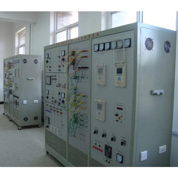
ZOPGDX-01 Factory Power Supply Technology Training Device
Factory power supply technology training device, 35KV total voltage voltage variable substation in the factory supply and distribution experiment system textbook, 10KV high -voltage substation and workshop electric load supply line -distribution line, microcomputer relay protection device, backup power supply supply, backup power supply, Automatically invest device, non -contribution automatic compensation device.
"Factory Power Supply Technology Tr*ning Device" is based on the "Advanced Electrical Technology", "Electrician Basics (Applicable to Senior Workers)", "Electrician Technician Tr*ning Materials" compiled by the Machinery Industry Vocational Skills Appr*sal Guidance Center, combined with "Factory Power Supply" and Developed and produced by the course " Power Supply and Distribution Technology". It m*nly focuses on the microcomputer relay protection devices, backup power automatic input devices, automatic reactive power compensation devices, and intelligent power supply and distribution lines involved in the 35kV total step-down substation, 10kV high-voltage substation and workshop power load in the textbook. The collection module and industrial human-machine interface are designed and developed for key teaching contents such as electrical primary, secondary, control, and protection. Through skill tr*ning in this tr*ning device, students can develop their practical skills while deeply understanding professional knowledge. . Moreover, this set of practical tr*ning equipment is also helpful for students to understand and master the working characteristics and wiring principles of transformers, motor units, current transformers, voltage transformers, analog meters, digital electric stopwatches and switching components. 2. Features 1. Strong practicality This device is designed based on typical teaching content. During development, suggestions from professional teachers were solicited and practical experience in engineering applications was absorbed. The practical skill tr*ning requirements for power reception, transmission, distribution, control, and protection of the factory power supply system are relatively systematically realized. During the practical tr*ning, students can also master the correct circuit switching operations, switching operations, operation control and adjustment procedures for various operation modes. The device has clear structure, flexible operation, convenient operation, safety and reliability. A good practical tr*ning platform has been established for students to improve their practical skills. 2. Strong comprehensiveness: This device integrates microcomputer line protection, microcomputer motor protection, automatic switching and reactive power compensation functions related to factory power supply. Industrial field products are used. The circuit model and the motor model can simulate the field conditions of the factory more typically, which is conducive to theoretical analysis and numerical analysis. 3. Advancement This device integrates microcomputer relay protection, industrial touch screen and PLC and other microcomputer function detection and control related technologies. It adopts a hierarchical distributed control method to form a comprehensive automation tr*ning integrating control, protection, measurement and signal. platform. It reflects the profound changes of current automation technology and communication technology in supply and distribution network. 3. Technical performance 1. Input power supply: three-phase four-wire ~ 380V ± 10% 50Hz ± 2% 2. Overall machine capacity: ≤ 3kVA 3. The tr*ning platform is made of iron matte dense spray plastic and aluminum panel (concave Character rotten board technology) 4. Table size: 1771mm × 1804mm × 726mm 5. Two communication interfaces, RS-485 and Ethernet; standard MODBUS communication protocol 6. Microcomputer protection device measuring element accuracy: scale error: no more than 1% ; Measurement current: 0.2 level; Bus voltage: 0.2 level; Output accuracy: 0.2 level; Frequency: 0.01HZ; P, Q, COSΦ; 0.5 level; Communication resolution: no more than 1ms
7. Teaching software
1. Electrical safety and electric shock first *d simulation teaching software
The software uses a combination of two-dimensional and three-dimensional virtual images to teach students the safety and first *d methods of using electricity. The software includes single-phase electric shock, two-phase electric shock, step electric shock, low-voltage electric shock first *d, high-voltage electric shock first *d, artificial respiration first *d, Principles of hand-holding breathing rescue method, chest cardiac compression and other protective methods are expl*ned and taught. Principles of single-phase electric shock are divided into rep*ring live disconnection, rep*ring socket electric shock, and outdoor electric shock. The teaching of low-voltage electric shock and high-voltage electric shock m*nly expl*ns and demonstrates to students how to rescue people who are suffering from low-voltage electric shock or high-voltage electric shock. Artificial respiration rescue method, hand-holding breathing rescue method, and chest cardiac compression rescue method are demonstrated using 3D virtual simulation technology. After rendering and Polish it to make the model look like the real part and look realistic. Through practical tr*ning, students can be educated on the safe use of electricity in the tr*ning room, improve students' safety awareness, and enable students to learn some self-rescue methods, so that students can take cert*n safety measures to protect themselves when encountering danger, and become familiar with various Causes of electrical accidents and practical measures to deal with them to reduce the occurrence of electrical accidents.
2. M*ntenance of electricians, electronic motors and vocational qualification tr*ning assessment simulation software
This software is in apk format and can be used on PC or mobile. This software can set faults manually or automatically. This software can manually set fault points through the green box in the circuit diagram (you can set up to 39 fault points), you can also automatically set one random fault point, two random fault points, three random fault points, four random fault points, and five random fault points through the system. It has functions such as toolbox, component library, magnifying glass, circuit diagram, etc. You can choose a multimeter for testing through the toolbox, select appropriate components through the component library, and clearly understand each component and circuit through the magnifying glass. This software allows students to understand the working principle and circuit structure of the motor star-delta start control circuit through the setting of faults in the motor star-delta start control circuit and various investigations.
3. Virtual spectrum analyzer, logic analyzer, oscilloscope, and three-meter simulation software:
This software is in apk format and can be used on PC or mobile terminals. The functions of this software are: resistance measurement, AC voltage measurement (measuring transformer, if the multimeter burns out when measuring the transformer, black smoke will emit prompts and can reset the multimeter), determine the polarity of the transistor, measure the DC voltage (the light turns on when the ammeter is turned on), measure the DC current, and determine the quality of the capacitor. This software can drag the red and black pen tips at will. When the two pen tips are dragged and positioned on the object to be measured, a red circle will be displayed. If the positioning is not accurate, no red circle will be displayed, and when incorrect operations are performed (such as the wrong range selected, If the measured data is wrong, etc.), the meter pointer will be unresponsive, prompting errors and re-measurement, etc. This multimeter can select AC voltage range, DC voltage range, resistance range, current range, resistance adjustment to 0, and can enlarge the display data. Clearly view the measured data size. Students can learn the correct use of multimeters through this software.
4. Microcontroller , PLC programmable design and control virtual simulation software:
This software is developed based on unity3d and has built-in experimental steps, experimental instructions, circuit diagrams, component lists, connection lines, power on, circuit diagrams, scene reset, return and other buttons. After the connections and codes are correct, you can start/stop, The forward movement and reverse movement buttons operate the 3D machine tool model to move. In the connected line state, the 3D machine tool model can be enlarged/reduced and translated.
1. Relay control: Read the experiment instructions and enter the experiment. By reading the circuit diagram, select the relays, thermal relays, switches and other components in the component list and drag and drop them into the electrical cabinet. The limiters are placed in the three-dimensional On the machine tool model, you can choose to cover it, and some component names can be renamed. Then click the Connect Line button to connect terminals to terminals. After successfully connecting the machine tool circuit, choose to turn on the power and proceed. If the component or line An error box will pop up if there is a connection error, and the scene can be reset at any time.
2. PLC control: The experiment is the same as relay control, with the addition of PLC control function. After the connection is completed, enter the program writing interface through the PLC coding button, and write two programs, forward and reverse, with a total of 12 ladder diagram symbols. The writing is completed. Finally, select Submit for program verification. After the verification is successful, turn on the power for operation. Error boxes will pop up for component, line connection, and code errors, and the scene can be reset at any time.
3. Single-chip microcomputer control: The experiment is the same as relay control, with the addition of single-chip microcomputer control function. After the connection is completed, enter the programming interface through the C coding button, enter the correct C language code, and after successful submission and verification, turn on the power for operation, components, lines If there are connection or code errors, an error box will pop up, and the scene can be reset at any time.
4. Practical tr*ning items
1. Cognition of the factory power supply electrical wiring diagram
(1) Cognition of the electrical m*n wiring simulation diagram of the tr*ning platform
(2) Correct operation of the touch screen
(3) Cognition of the electrical m*n wiring diagram
2. Factory transformation On-duty skills tr*ning in power distribution room
(1) Wiring method of current transformer and voltage transformer
(2) Transformer on-load voltage regulation
(3) Line power outage operation
(4) Transformer switching operation
(5) Busbar switching operation
3 .Microcomputer relay protection of high-voltage lines in factories
(1) Simulate normal, maximum and minimum operating modes of the system
(2) Simulate system short circuit
(3) Correct operation of electric stopwatch
(4) Microcomputer line protection device parameter setting operation
(5) No time limit Current quick-break protection
(6) Current quick-break protection with time limit
(7) Definite time overcurrent protection
(8) Inverse time overcurrent protection
(9) Current and voltage ch*n protection
4. Relay protection of high-voltage motors
(1) Frequency converter parameter setting operation
(2) Open-loop speed regulation tr*ning of frequency converter
(3) Starting method of three-phase asynchronous motor
(4) Parameter setting operation of microcomputer motor protection device
(5) Quick-break protection of high-voltage motor
(6) Inverse time overcurrent of high-voltage motor Protection
(7) Simulate motor outlet short circuit
(8) Microcomputer motor protection device parameter setting operation
(9) Quick-break protection of high-voltage motor
(10) Inverse time overcurrent protection of high-voltage motor
5. Automatic device tr*ning of factory power supply system
(1) Parameter setting operation of automatic backup power supply input device
(2) Automatic input of backup power supply
(3) Parameter setting operation of reactive power compensation device
(4) Automatic reactive power compensation function
(5) Test of backup input conditions
(6) Incoming line backup (clear) Standby) and adaptive
(7) Bus joint standby (dark standby) and adaptive
(8) Reactive power compensation device recognition
(9) Automatic reactive power compensation
6. Factory power supply monitoring tr*ning
1) SCADA monitoring.
2) Four remote (remote signaling, remote control, telemetry, remote adjustment) experiment.
3) Fault recording.
4) Event record query.
- Previous:ZOPDLJB-06 Electric Power System Relay Protection Working Device
- Next:ZOPDJZP-02 Multi-Electrical Architecture Training Device