News
News
- Excavator steering system anatomy training desk
- Hydraulic front hanging mechanical experimental device
- Water pump performance experimental device
- Contact oxidation pool training desk
- Drinking water treatment process training desk
- Reverse osmosis membrane training
- Softness and salt removal experimental device
- Salvation tank experimental device
- Aerobic biological treatment training device
- Bio -turntable principle experimental device
- Lucky ratio blocking test device
- Socci condiment training desk
- Industrial wastewater treatment training desk
- Industrial wastewater treatment process simulation experimental device
- CNC milling machine installation and maintenance training table
- CNC Machining Center Maintenance and Processing Technical Experimental Desk
- AC Voltage Merragatory System Electrical Experiment Device
- Solar power generation experimental device
- Electrical experimental device of ship anchor machine
- Worker Electrical Engineering Technology Training Device
Contact us
WeChat:15372285263
Phone:15372285263
WhatsApp:15372285263
Address:Building 3, No. 7 Longyuan Road, Shuige Industrial Park, Liandu District, Lishui City, Zhejiang Province
News
Pharmaceutical Engineering Experiment
Author:
Time:2024-02-15
Hits:
Pharmaceutical Engineering Experiment,Material Sorting PLC Control Experiment
Device function:

Pharmaceutical Engineering Experiment,Material Sorting PLC Control Experiment
Device function:
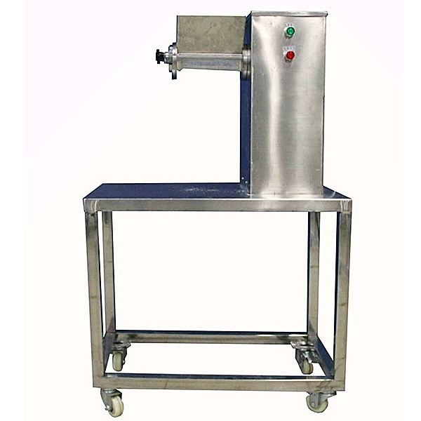
1. Understand and master the structure and standard operating procedures for the swaying granulator.
2. Familiar with the standard operating procedures for gr--n -making positions. The m--n points of quality control and production management. Determine the quality of the particles correctly.
3. Learn to clear the field correctly, clean the mixed equipment correctly, and fill in the production records of the granularity position correctly.
Technical Parameters:
Diameter of the drum: φ60mm
Root speed: 46 rpm/cents
Swing amplitude:> 360
Production capacity: 20-30kg/h
Work power: 0.37kW
Shape size: 800 × 450 × 1500mm, a mobile design with a double brake wheel.

Pharmaceutical Engineering Experiment,Material Sorting PLC Control Experiment
Note: PLC, inverter can be configured separately, or you can also use the PLC inverter speed adjustment tr--ning device to use
Equipment structure:
Material sorting and control tr--ning model is a metal structure. The I/O terminal of the PLC module, the wiring terminal of the inverter, the connection terminals of each commonly used module and the connecting terminal are connected to the safe socket. The circuit of the instruction switch, the photoelectric switch, and the indicator element is connected through the terminal row. The combination of the plug -in -line connection circuit and the terminal brand connection circuit not only ensure the tr--ning, formation and consolidation of the basic skills of students, but also to ensure the rapid, safe and reliable circuit connection.
Technical Parameters
Power: single phase AC220V, 50Hz
Power: <200W
Size: not less than 800*515*220mm
Some tr--ning items:
1. Installation and debugging of the pneumatic system
(1) Installation of the dynamic direction control circuit (2) Installation of the pneumatic speed control circuit
(3) Installation of pneumatic order control loop (4) Connection of pneumatic system gas path
(5) Position adjustment of magnetic switch (6) Pneumatic system debugging
2. Installation and debugging of the inverter (need to be equipped with a variable converter)
(1) Connection of the m--n circuit of the inverter and AC motor (2) The parameter settings and operation of the inverter panel
(3) Inverter panel control AC motor speed regulation (4) Control motor start -stop through the external terminal of the inverter
- Previous:Liquid thermal conductivity testing experiment table
- Next:Training device of water flow turbulence
Recommended information
Recommended Products