Product
News
- Excavator steering system anatomy training desk
- Hydraulic front hanging mechanical experimental device
- Water pump performance experimental device
- Contact oxidation pool training desk
- Drinking water treatment process training desk
- Reverse osmosis membrane training
- Softness and salt removal experimental device
- Salvation tank experimental device
- Aerobic biological treatment training device
- Bio -turntable principle experimental device
- Lucky ratio blocking test device
- Socci condiment training desk
- Industrial wastewater treatment training desk
- Industrial wastewater treatment process simulation experimental device
- CNC milling machine installation and maintenance training table
- CNC Machining Center Maintenance and Processing Technical Experimental Desk
- AC Voltage Merragatory System Electrical Experiment Device
- Solar power generation experimental device
- Electrical experimental device of ship anchor machine
- Worker Electrical Engineering Technology Training Device
Contact us
WeChat:15372285263
Phone:15372285263
WhatsApp:15372285263
Address:Building 3, No. 7 Longyuan Road, Shuige Industrial Park, Liandu District, Lishui City, Zhejiang Province
uncategorized
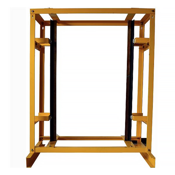
ZOPDT-102C-1 Elevator Guide Rail Installation, Disassembly and Debugging Training Device
Elevator guide rail installation and disassembly and debugging training device, elevator guide rail installation training platform
1. Equipment size: 1200×800×1500.
2. Equipment includes:
a: Support frame - assembled by angle steel, epoxy polyplastic sprayed on the surface, beautiful and durable, the integral bracket feet are equipped with casters for easy movement.
b: Guide r*l - 3kg hollow guide r*l, 50×50×5# angle steel, 10# channel steel for the bottom beam of the bottom frame.
c: Virtual simulation system for comprehensive integrated tr*ning of professional skills The model
in the software can be rotated 360°, enlarged, reduced, and translated, and has universal interactive buttons: return, home page, help. There are prompts for all virtual simulation task processes, and the software automatically ticks after completing a task. There are experimental tasks 1 and basic solids above the tool library ( the XYZ space coordinate icon automatically rotates with the rotation when the model is rotated.) A. Plane solids: The experimental steps are divided into experimental tasks (text prompt tasks) - build models (drag the model in the tool library to the three-projection surface system, and the projection will be automatically displayed. There will be prompts when the selection is wrong) - change posture (change by clicking the up, down, left, and right arrows) - select projection (enter the answering interface, and select the three-dimensional projection diagram completed at this time from the 6 items) B. Cutting solids: The experimental steps are divided into experimental tasks (text prompt tasks) - build models (drag the model in the tool library to the three-projection surface system, and the projection will be automatically displayed) - mark the projection situation (mark the three-dimensional projection diagram, and select the corresponding marking symbol in the 14 blank columns) C. Intersecting solids: The experimental steps are divided into experimental tasks (text prompt tasks) - digging holes (select any digging hole model, then you can select any surface in the XYZ space coordinates, the models will switch at the same time, and a coordinate slider will appear. According to the displacement of the slider, the model will have a corresponding degree of cross-section) - aperture change (select 1-4 apertures) - rear through hole - select projection (enter the answering interface, and select the completed three-dimensional projection diagram at this time in 8 items) 2. Assembly A. Assembly assembly: The experimental steps are divided into experimental tasks (text prompt tasks) - select the assembly model (8 models can be selected) - assemble the assembly (select the tool library model according to the selected model and drag and drop the assembly) - section the assembly (you can select any surface in the XYZ space coordinates, the models will switch at the same time, and a coordinate slider will appear. According to the displacement of the slider, the model will have a corresponding degree of cross-section) - select side projection (enter the answering interface, based on the known front and horizontal projection diagrams, select the correct side projection diagram in 3 items) B. Assembly drawing reading: The experimental steps are divided into experimental tasks (text prompt tasks) - select the assembly section view (8 types of drawings can be selected) - build the assembly model (select the tool library model according to the selected model and drag and drop the combination) - cut the assembly (you can select any surface in the XYZ space coordinates, the model will switch at the same time, and a coordinate slider will appear. According to the displacement of the slider, the model will appear with a corresponding degree of section) - select the left view (enter the answer interface, according to the known m*n view and top view, select the correct left view from the 3 items) 3. Assembly A. Mechanical transmission mechanism : 8 mechanisms (worm gear, gear rack, spiral transmission, plane external meshing gear, plane internal meshing gear, space spur bevel gear, belt drive , ch*n drive) are optional. After selecting, the model will appear in the toolbar. Drag the model freely to combine. After the combination is completed, the model can be operated. Each mechanism comes with an introduction, video demonstration, and drawing method. There are 6 questions in the answer interface, and each question has 4 options. B. Gear oil pump: Select the tool library model according to the prompts and build the model step by step. You can choose to learn the introduction, drawing method, and animation principle (the internal movement principle of the model can be visualized). There are 2 questions in the answering interface, and 4 options for each question. C. Mechanical mechanism construction: 2 mechanisms (2-degree-of-freedom robotic arm, 3-degree-of-freedom robotic arm). Select the tool library model according to the prompts and build the model step by step. After the combination is completed, the model can be operated. Each mechanism has an introduction and video demonstration. There are 2 questions in the answering interface (both models must be built before entering), and 4 options for each question. 3. The equipment can achieve the following teaching objectives: a. Understand the structure and installation principle of elevator guide r*ls. b. The guide r*ls can be disassembled and the verticality of the guide r*ls can be adjusted.
- Previous:ZOPDT-102C-5 elevator door installation and disassembly and debugging training device
- Next:ZOPDT-102C-3 elevator safety clamp installation and disassembly and debugging training device
Recommended Products