Product
News
- Excavator steering system anatomy training desk
- Hydraulic front hanging mechanical experimental device
- Water pump performance experimental device
- Contact oxidation pool training desk
- Drinking water treatment process training desk
- Reverse osmosis membrane training
- Softness and salt removal experimental device
- Salvation tank experimental device
- Aerobic biological treatment training device
- Bio -turntable principle experimental device
- Lucky ratio blocking test device
- Socci condiment training desk
- Industrial wastewater treatment training desk
- Industrial wastewater treatment process simulation experimental device
- CNC milling machine installation and maintenance training table
- CNC Machining Center Maintenance and Processing Technical Experimental Desk
- AC Voltage Merragatory System Electrical Experiment Device
- Solar power generation experimental device
- Electrical experimental device of ship anchor machine
- Worker Electrical Engineering Technology Training Device
Contact us
WeChat:15372285263
Phone:15372285263
WhatsApp:15372285263
Address:Building 3, No. 7 Longyuan Road, Shuige Industrial Park, Liandu District, Lishui City, Zhejiang Province
uncategorized
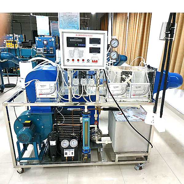
ZOPLR-BLQ surface cooler performance experimental device
Cooler performance test bench, spray chamber air cooler test training device. Master the methods of measuring the temperature, relative humidity and resistance characteristics of the spray chamber and cooler; be familiar with the determination methods of heat transfer, heat exchange efficiency coefficient and contact coefficient.
1. Product application scope:
It can be used to understand the composition of the water spray chamber and *r surface cooler, deepen the difference between the performance of direct contact and surface heat and moisture exchange equipment through experiments, master the methods of measuring the temperature, relative humidity and resistance characteristics of the water spray chamber and surface cooler; be familiar with the determination methods of heat exchange, heat exchange efficiency coefficient and contact coefficient.
2. Product use working environment:
2.1 Working environment temperature: 0-40℃.
2.2 Working environment humidity: < 80% (no condensation).
2.3 Power supply: single-phase 220V, 50 Hz.
3. Technical and performance parameters:
3.1 Cold water system: compressor, condenser, evaporator coil, high-pressure water pump, flow meter, water spray chamber, nozzle, surface cooler, constant temperature room, low-noise fan, humidifier, electric heater.
3.2 Measurement and control system: temperature control instrument, temperature measuring instrument, digital current and voltage meter, micro pressure meter, flute tube).
3.3 Other parameters
*r duct cross-sectional dimensions: 250*250mm
Compressor: 1000W, cooling capacity 2730W Brand: Hitachi 1.5P
Water pump: self-priming jet pump, Q=4.2m3/h, H=35m, N= 370W, voltage 220V, 50Hz
Centrifugal fan: motor power 750W Voltage 220V *r volume 2850m3/h Full pressure 490Pa Speed 1400r/m Low noise fan
Refrigerant: R22
Flow meter: rotor flow meter caliber DN15, flow range 40-400L/h
3.4 Single chip microcomputer , PLC programmable design and control virtual simulation software:
This software is developed based on Unity3D, with built-in experimental steps, experimental instructions, circuit diagrams, component lists, connection lines, power on, circuit diagrams, scene reset, return and other buttons. After the connection and code are correct, the 3D machine model can be operated through the start/stop, forward motion, and reverse motion buttons . When the line is connected, the 3D machine model can be enlarged/reduced and translated.
1. Relay control: Read the experimental instructions and enter the experiment. By reading the circuit diagram, select relays, thermal relays, switches and other components in the component list and drag and drop them into the electrical cabinet. The limiter is placed on the 3D machine model. You can choose to cover the lid. Some component names can be renamed. Then click the connection line button to connect the terminals to the terminals. After the machine circuit is successfully connected, choose to turn on the power and operate. If the component or line connection is wrong, an error box will pop up, and the scene can be reset at any time.
2. PLC control: The experiment is the same as relay control, with the addition of PLC control function. After the connection is completed, press the PLC coding button to enter the program writing interface, and write two programs, forward and reverse. There are 12 ladder diagram symbols in total. After writing, select Submit to verify the program. After successful verification, turn on the power to operate. Error boxes will pop up for components, line connections, and code errors, and the scene can be reset at any time.
3. MCU control: The experiment is the same as relay control, with the addition of MCU control function. After the connection is completed, press the C coding button to enter the programming interface, enter the correct C language code, and submit for successful verification. Turn on the power to operate. Error boxes will pop up for components, line connections, and code errors, and the scene can be reset at any time.
4. System configuration list
| Serial number | name | Specifications | quantity |
| 1 | Surface cooling section | 1 set | |
| 2 | Spray Room | 1 set | |
| 3 | Constant temperature room | 1 set | |
| 4 | Fan | CF-11 | 1 set |
| 5 | Refrigeration Compressors | 12M2 | 1 set |
| 7 | Vertical liquid reservoir | 1HP | 1 |
| 8 | Coil evaporator | 1 set | |
| 9 | St*nless steel water pump | 370W | 1 set |
| 10 | Flow Meter | LZB-15 | 1 |
| 11 | humidifier | GO-2028 | 1 set |
| 12 | Measurement and control systems | 1 set |
- Previous:ZOPLR-M1 Visual Refrigeration Cycle Demonstration Experimental Device
- Next:ZOPJYD-11F water-cooled refrigerator performance comprehensive experimental device
Recommended Products