Product
News
- Excavator steering system anatomy training desk
- Hydraulic front hanging mechanical experimental device
- Water pump performance experimental device
- Contact oxidation pool training desk
- Drinking water treatment process training desk
- Reverse osmosis membrane training
- Softness and salt removal experimental device
- Salvation tank experimental device
- Aerobic biological treatment training device
- Bio -turntable principle experimental device
- Lucky ratio blocking test device
- Socci condiment training desk
- Industrial wastewater treatment training desk
- Industrial wastewater treatment process simulation experimental device
- CNC milling machine installation and maintenance training table
- CNC Machining Center Maintenance and Processing Technical Experimental Desk
- AC Voltage Merragatory System Electrical Experiment Device
- Solar power generation experimental device
- Electrical experimental device of ship anchor machine
- Worker Electrical Engineering Technology Training Device
Contact us
WeChat:15372285263
Phone:15372285263
WhatsApp:15372285263
Address:Building 3, No. 7 Longyuan Road, Shuige Industrial Park, Liandu District, Lishui City, Zhejiang Province
uncategorized
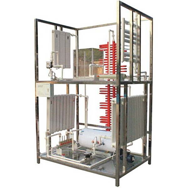
ZOPLR-DJL Unit Residential Building Household Heat Metering Heating System Experimental Device
The training device for the household heat metering heating system in a unit residential building and the heating training table demonstrate the appearance, structure, principle, installation location and installation form of the single-pipe leapfrog heating system and the double-pipe down-supply and down-return heating system.
I. Tr*ning functions
1. Integral full-scale radiators and pipes, transparent floor, can clearly see the entire structure and direction of hidden pipes.
2. Heat meters are set on the first and second floors, and the entire system is demonstrated by boilers and circulating pumps to achieve heat circulation.
3. The appearance, structure, principle, installation location and installation form of the single-pipe spanning heating system and the double-pipe down-supply and down-return heating system are displayed.
4. The appearance, structure, principle, installation location and installation form of copper-aluminum composite radiators, thin-walled steel pipe radiators (artistic shapes), ordinary steel radiators, plate-wing radiators, and small backpack radiators in the bathroom are displayed.
5. The expansion tank is made of fully transparent materials, which can demonstrate the working principle of the expansion tank.
6. All radiators and water heating equipment can be fully demonstrated.
7. Single-chip microcomputer , PLC programmable design and control virtual simulation software:
This software is developed based on Unity3D, with built-in experimental steps, experimental instructions, circuit diagrams, component lists, connection lines, power on, circuit diagrams, scene reset, return and other buttons. After the connection and code are correct, the 3D machine tool model can be operated by the start/stop, forward motion, and reverse motion buttons. When the line is connected, the 3D machine tool model can be enlarged/reduced and translated.
1. Relay control: Read the experimental instructions and enter the experiment. By reading the circuit diagram, select relays, thermal relays, switches and other components in the component list and drag and drop them to the electrical cabinet. The limiter is placed on the 3D machine tool model. You can choose to cover the cover. Some component names can be renamed. Then click the connection line button to connect the terminals to the terminals. After the machine tool circuit is successfully connected, choose to turn on the power and operate. If the component or line connection is wrong, an error box will pop up, and the scene can be reset at any time.
2. PLC control: The experiment is the same as relay control, with the addition of PLC control function. After the connection is completed, enter the program writing interface through the PLC coding button, write two programs, forward and reverse, with a total of 12 ladder diagram symbols. After writing, select Submit to verify the program. After successful verification, turn on the power to operate. Errors in components, line connections, and code will pop up prompt error boxes, and the scene can be reset at any time.
3. MCU control: The experiment is the same as relay control, with the addition of MCU control function. After the connection is completed, enter the programming interface through the C coding button, enter the correct C language code, and submit the verification successfully. Turn on the power to operate. Errors in components, line connections, and code will pop up prompt error boxes, and the scene can be reset at any time.
Technical indicators
Dimensions: 1500×1000×2400mmFrame
material: 304 st*nless
steelFloor material: tempered glassWater
inlet requirements: 0.05MPa~0.75MPaSafety
protection: with automatic leakage protection device and grounding protection
M*n configuration
Heat meters and valves are installed at the entrances of the first and second floors. The heating system on the first floor is a single-pipe spanning heating system. Copper-aluminum composite radiators, thin-walled steel pipe radiators (artistic shapes), and ordinary steel radiators are set on the left, middle, and right three frame walls; the heating system on the second floor is a double-pipe down-supply and down-return system. The radiators on the left, middle, and right are plate-wing radiators, thin-walled steel pipe radiators (artistic shapes), and small backpack radiators in the bathroom. The m*n riser for water supply and return is set along the left side of the frame.
Tr*ning projects
Tr*ning 1: Demonstration of the operation of the heat metering heating system for individual residential buildings
Tr*ning 2: Understanding of the single-pipe leap-over heating system
Tr*ning 3: Understanding of the double-pipe down-supply and down-return heating system
Tr*ning 4: Metering operation and disassembly and assembly tr*ning of the heat meter
Tr*ning 5: Disassembly and assembly and operation tr*ning of the boiler
Tr*ning 6: Operation and disassembly and assembly tr*ning of the circulation pump
Tr*ning 7: Operation and disassembly and assembly tr*ning of the water distributor and water collector
Tr*ning 8: Disassembly and assembly tr*ning of thin-walled steel pipe radiators
Tr*ning 9: Disassembly and assembly tr*ning of copper-aluminum composite radiators
Tr*ning 10: Disassembly and assembly tr*ning of ordinary steel radiators
Tr*ning 11: Disassembly and assembly tr*ning of the small backpack radiator in the bathroom
Tr*ning 12: Disassembly and assembly tr*ning of the plate-wing radiator
- Previous:ZOPLR-DGN multifunctional refrigeration technology experimental device
- Next:ZOPLR-XZL New multifunctional refrigeration technology comprehensive assessment experimental device
Recommended Products