Product
News
- Excavator steering system anatomy training desk
- Hydraulic front hanging mechanical experimental device
- Water pump performance experimental device
- Contact oxidation pool training desk
- Drinking water treatment process training desk
- Reverse osmosis membrane training
- Softness and salt removal experimental device
- Salvation tank experimental device
- Aerobic biological treatment training device
- Bio -turntable principle experimental device
- Lucky ratio blocking test device
- Socci condiment training desk
- Industrial wastewater treatment training desk
- Industrial wastewater treatment process simulation experimental device
- CNC milling machine installation and maintenance training table
- CNC Machining Center Maintenance and Processing Technical Experimental Desk
- AC Voltage Merragatory System Electrical Experiment Device
- Solar power generation experimental device
- Electrical experimental device of ship anchor machine
- Worker Electrical Engineering Technology Training Device
Contact us
WeChat:15372285263
Phone:15372285263
WhatsApp:15372285263
Address:Building 3, No. 7 Longyuan Road, Shuige Industrial Park, Liandu District, Lishui City, Zhejiang Province
Mechanical Basic
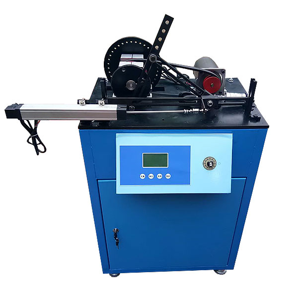
ZOPJX-FLD series mechanical dynamics flywheel speed adjustment experiment platform
Mechanical dynamic flywheel speed regulating experimental desk, mechanical speed fluctuation experimental device working status movement speed fluctuation experiment: familiar with the test method of working resistance when the unit operates, understand the effects and reasons of the dynamic load on the speed fluctuation of the mechanical system.
ZRJX-FLD-1 flywheel speed regulation innovative combination test bench
1. Experimental objectives
1) Meet the mechanical speed fluctuation test simulation experiment. Adjust the speed to observe the speed fluctuation phenomenon of the machine, solve the uneven coefficient of system operation, and draw the comparison curve between actual measurement and simulation.
2) Meet the mechanical speed fluctuation adjustment experiment. Change the size of the flywheel and the size of the working resistance respectively, observe the changes in mechanical speed fluctuations, and compare and analyze with the theoretical calculation results, and then master the adjustment methods and design indicators of periodic speed fluctuations, master the flywheel design method and calculate the flywheel inertia.
2. Performance characteristics:
1) Equipped with large and small flywheels, the speed regulating effects of different flywheel qualities can be compared.
2) Equipped with springs with different stiffnesses as the working resistance of the slider, test and compare the working resistance and speed fluctuation of mechanical operation under different load conditions.
3) The speed of the working mechanical system is adjustable to test and compare the speed fluctuations at different speeds and the speed regulation effect at different speeds.
4) Ensure that the various moving components that make up the experimental bench have good matching clearance and long service life.
3. M*n technical parameters:
1 large flywheel φ175×28;
1 small flywheel φ145×25;
base circle radius r=40mm push rod lift h=15;
1 DC speed regulating motor with voltage 220V; N=125W speed n =1500r/min; 2
angular displacement sensors
; output voltage/number of pulses: 5V/1000P, 5V/360P;
1 software CD;
overall size: 500X600X460mm
ZRJX-FLD-2 mechanical dynamics flywheel speed control experimental bench The
experimental bench adopts The most typical small punch structure with flywheel speed regulation in engineering applications was used as the experimental object, and innovative designs were made on its components. It was designed into an innovative combination test bench with adjustable punching force, flywheel inertia, and convertible working resistance mode of the unit, making the experiment The test object can be transformed according to the working resistance mode. By replacing a few simple parts on the experimental bench, the mechanical structure of the experimental bench can be changed. The experimental bench is converted from a punch structure bench to a press structure bench. The working resistance form is changed from the impact force mode to the crankshaft angle in a random group. Linear changing pressure change mode, and can change the impact force or pressure change value. Analyze and study the dynamics of mechanical systems by measuring the smooth motion patterns and starting and braking characteristics of flywheels in different working resistance modes.
Experiment content
(1) Experiment on stable movement speed fluctuation of the unit in non-working state: Understand the working principle of the photoelectric encoder, master the testing method of system speed fluctuation
, and understand the reasons for periodic fluctuations in speed when the unit is operating stably.
(2) Movement speed fluctuation experiment of the unit in working condition: Be familiar with the testing method of working resistance when the unit is running, and understand the impact and causes of dynamic load on the speed fluctuation of the mechanical system.
(3) Unit starting and braking speed fluctuation test experiment.
(4) Unit starting and braking time test experiment.
(5) Testing and analysis calculation experiments of the maximum profit and loss of mechanical energy.
(6) Mechanical speed fluctuation adjustment experiment: Change the size of the flywheel, observe the changes in mechanical speed fluctuation, and compare and analyze it with the theoretical calculation results to master the adjustment methods and design indicators of periodic speed fluctuations. Use experimental data to calculate the equivalent moment of inertia of the flywheel, and master the design methods of the flywheel to design the flywheel.
(7) Kinematic analysis experiment of crank slider.
M*n technical parameters
(1) Pressing force sensor range: 0~5000N Accuracy: 0.5%
(2) Motor torque sensor range: 0~100N Accuracy: 0.5%
(3) Grating angular displacement sensor: Output voltage: 5V Number of pulses: 360P
(4) Motor rated power: P=180W
(5) Motor speed: 1400r/min
(6) Power supply: 220V AC/50HZ
(7) Overall dimensions: 590×560×610 (mm)
(8) Weight: 90kg
- Previous:ZOPJX-CL series slot wheel mechanism experimental platform
- Next:ZOPJX-YGC series curved rocker rocker dynamic testing and design experimental platform
Recommended Products