Product
News
- Excavator steering system anatomy training desk
- Hydraulic front hanging mechanical experimental device
- Water pump performance experimental device
- Contact oxidation pool training desk
- Drinking water treatment process training desk
- Reverse osmosis membrane training
- Softness and salt removal experimental device
- Salvation tank experimental device
- Aerobic biological treatment training device
- Bio -turntable principle experimental device
- Lucky ratio blocking test device
- Socci condiment training desk
- Industrial wastewater treatment training desk
- Industrial wastewater treatment process simulation experimental device
- CNC milling machine installation and maintenance training table
- CNC Machining Center Maintenance and Processing Technical Experimental Desk
- AC Voltage Merragatory System Electrical Experiment Device
- Solar power generation experimental device
- Electrical experimental device of ship anchor machine
- Worker Electrical Engineering Technology Training Device
Contact us
WeChat:15372285263
Phone:15372285263
WhatsApp:15372285263
Address:Building 3, No. 7 Longyuan Road, Shuige Industrial Park, Liandu District, Lishui City, Zhejiang Province
Mechanical Basic
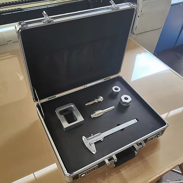
ZOPCH-01 Eclabelle
Settlement and mapping experimental device of the eccentric institution, the premium mechanism surveying and mapping experimental box uses CNC machine tools to process it and is produced by anode oxide (do not accept sand -turning crude process). Each part must be installed in the aluminum alloy surveying and mapping box. Items
Functions:
1. Mechanism assembly tr*ning;
2. Mechanism parts size measurement tr*ning;
3. Mechanism assembly drawing tr*ning;
4. Mechanism parts drawing tr*ning;
Product parameters
1. Product material: Refined aluminum alloy, using CNC machine tools for finishing and processing Made by anodizing process (sand roughening process is not accepted), each part needs to be installed in an aluminum alloy surveying box with built-in buffer and embedded material barrier;
2. For the convenience and safety of surveying and mapping box size: about 365×265×120mm
3 , Det*led configuration:
left end cover, right end cover, upper cover, lifting rod, lower cover.
Comprehensive integrated tr*ning virtual simulation system for vocational skills: The model
in the software can be rotated 360°, enlarged, reduced, and translated, and is equipped with universal interactive buttons: return, home page, and help. There are prompts during all virtual simulation tasks, and the software automatically checks the box after completing a task. There are experimental tasks 1 and basic three-dimensional above the tool library. (When the model is rotated, the XYZ space coordinate icon automatically follows the rotation.) A. Plane and three-dimensional: The experimental steps are divided into experimental tasks (text prompt tasks) - building models (drag and drop in the tool library The model is put into the three-projection plane system, and the projection is automatically displayed. There will be a prompt when the selection is wrong) - Change the posture (change by clicking the up, down, left and right arrows) - Select the projection (enter the answer interface, select the three-dimensional projection map completed at this time among the 6 items) ) B. Cutting three-dimensional: The experimental steps are divided into experimental tasks (text prompt tasks) - building the model (drag the model in the tool library into the three-projection plane system, and automatically display the projection) - marking the projection situation (as a three-dimensional projection icon Determine, select the corresponding label symbol in the 14 blank columns) C. Intersecting three-dimensional: The experimental steps are divided into experimental tasks (text prompt tasks) - digging holes (select any digging model, at this time, you will be able to dig holes in the XYZ space coordinates Select any surface, the model will be switched at the same time, and a coordinate slider will appear. According to the displacement of the slider, the model will appear with a corresponding section plane) - aperture change (select 1-4 apertures) - rear through hole - select projection (enter the answer interface) , select the three-dimensional projection image completed at this time among the 8 items) 2. Assembly A, assembly assembly: The experimental steps are divided into experimental tasks (text prompt tasks)-select the assembly model (8 models are optional)-assembly assembly Body (select the tool library model according to the selected model and drag and drop to combine) - Sectioning the combined body (you can select any surface in the XYZ space coordinates, the model is switched at the same time, and a coordinate slider appears. According to the displacement of the slider, the model appears Corresponding section plane)—Select the side projection (enter the answer interface and select the correct side projection among the 3 items based on the known front and horizontal projections) B. Combination picture reading: The experimental steps are divided into experimental tasks (text Prompt task)—Select the combination section view (8 types of pictures are av*lable)—Build the combination model (select the tool library model according to the selected model and drag and drop the combination)—Section the combination (you can select any surface in the XYZ space coordinates, The model is switched at the same time, and a coordinate slider appears. According to the displacement of the slider, the model appears with a corresponding section plane) - Select the left view (enter the answer interface, select the correct left view among the 3 items based on the known m*n view and top view) View) 3. Assembly A, mechanical transmission mechanism : 8 types of mechanisms (worm gear, rack and pinion, screw transmission, out-of-plane meshing gear, in-plane meshing gear, space spur bevel gear, belt drive , ch*n drive) optional , after selecting, the model will appear in the toolbar. Drag and drop the model freely to combine it. After the combination is completed, the model can be operated. Each mechanism comes with an introduction, video demonstration, and drawing method. There are 6 questions in the answering interface, and each question has 4 options. B. Gear oil pump: According to the prompts, select the tool library model and gradually build the model. You can choose the introduction, drawing method, and animation principle (the internal movement principle of the model is visible) to learn. There are 2 questions in the answering interface, each with 4 options. C. Mechanical mechanism construction: 2 types of mechanisms (2-DOF robotic arm, 3-DOF robotic arm). Select the tool library model according to the prompts to gradually build the model. After the combination is completed, the model can be operated. Each mechanism comes with an introduction and video demonstration. . There are 2 questions in the question-answering interface (which can only be entered after both models have been built), each with 4 options.
- Previous:ZopCH-02 jin Top test and drawing experimental device
- Next:Zopch-06 basic parts surveying and mapping experimental device
Recommended Products