Product
News
- Excavator steering system anatomy training desk
- Hydraulic front hanging mechanical experimental device
- Water pump performance experimental device
- Contact oxidation pool training desk
- Drinking water treatment process training desk
- Reverse osmosis membrane training
- Softness and salt removal experimental device
- Salvation tank experimental device
- Aerobic biological treatment training device
- Bio -turntable principle experimental device
- Lucky ratio blocking test device
- Socci condiment training desk
- Industrial wastewater treatment training desk
- Industrial wastewater treatment process simulation experimental device
- CNC milling machine installation and maintenance training table
- CNC Machining Center Maintenance and Processing Technical Experimental Desk
- AC Voltage Merragatory System Electrical Experiment Device
- Solar power generation experimental device
- Electrical experimental device of ship anchor machine
- Worker Electrical Engineering Technology Training Device
Contact us
WeChat:15372285263
Phone:15372285263
WhatsApp:15372285263
Address:Building 3, No. 7 Longyuan Road, Shuige Industrial Park, Liandu District, Lishui City, Zhejiang Province
Mechanical Basic
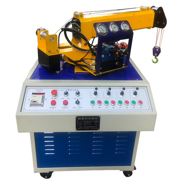
ZOPYY-QZJ crane ligament hydraulic system training device
The training device of the crane hydraulic system, the experimental platform of the crane hydraulic system is made from the real structure and narrowing proportion of the derivative, which can truly reflect the actual operating conditions of the machinery, so that students can deeply understand the structure and the structure and the structure of the components of the institutions in the experiment. working principle.
A truck crane is a self-propelled lifting machine that uses a tire-type basic vehicle as a carrier and is equipped with lifting equipment working devices and operating mechanisms. It is a widely used type of engineering machinery . It is suitable for lifting and lifting operations in large-scale outdoor construction projects, such as construction sites
1. Experimental items
1. Observation of the structure and working principle of each component of the hydraulic
transmission, and disassembly and assembly experiments. 2. Hydraulic lifting machinery demonstration control experiment.
3. PLC software simulation demonstration and control experiment.
4. Programmable controller (PLC) electrical control experiment: mechanical-electrical-hydraulic integrated control experiment.
2. Experiment content
1. Hoisting machinery demonstration control experiment
Rotation "lifting and contraction" luffing "lifting"
2. Programmable controller (PLC) electrical control experiment: mechanical-electrical-hydraulic integrated control experiment.
1) PLC instruction programming , Ladder diagram programming learning;
2) Learning and use of PLC programming software;
3) Communication and online debugging between PLC and computer;
4) Application of PLC in hydraulic transmission control and optimization of control scheme 3.
Performance and characteristics
1. The experimental bench is made of cold-rolled steel plates (and treated with plastic spraying and anti-corrosion), with a desktop structure and integrated control and push operations.
2. The electrical operation control is bottom-mounted, and the hydraulic station is placed in the m*n cabinet of the hydraulic bench. The overall structure is compact and coordinated. , the layout is beautiful and practical, and can be used for experiments by 4-6 people.
3. The lifting machine has an all-metal structure that is scaled down to the actual scale. During the experiment, the hydraulic system is started to operate the machine according to the experimental requirements.
4. Lifting . The machinery is made according to the structure and scale of the real thing, which can truly reflect the actual working conditions of the machinery, allowing students to deeply understand the structure and working principles of each component of the mechanism during the experiment.
5. The experimental control adopts manual control. and automatic control.
6. The experimental components are made of pressure-resistant hoses, and the pressure can reach 25Mpa.
7. With three-phase leakage protection, the output voltage is 380V/220V. If the leakage current to the ground exceeds 30mA, the power supply will be cut off; the electrical control adopts DC 24V. Power supply, with overvoltage protection to prevent misoperation from damaging the equipment.
8. Hydraulic and pneumatic transmission design and control virtual simulation software.
This software is developed based on unity3d. The software adopts the form of three-dimensional roaming, and the movement can be controlled by the keyboard and the lens direction can be controlled by the mouse. The interface has homepage, help, full screen, component recognition, circuit construction, key component testing, and typical system testing interfaces.
1. Component recognition uses the form of automatic playback to introduce the m*lbox, liquid level gauge, and oil pump unit on the equipment. Here we introduce the pop-up hydraulic symbols, principles and introduction, click OK to enter the next introduction), valve frame, pressure gauge, sensor , etc.
2. Component disassembly and assembly are divided into learning mode and assessment mode, built-in electromagnetic reversing valve, plate overflow Valve, plunger pump, filter valve, electro-hydraulic servo valve, the disassembly sequence is prompted and highlighted in the learning mode. There is no prompt for disassembly and installation in the assessment mode. If the disassembly and assembly sequence is wrong, the next step of disassembly and assembly will not be possible. . The toolbar is equipped with draggable seals, pumps, valves, oil filters, hex wrenches, pipe wrenches, adjustable wrenches, and M5 screws.
3. The hydraulic components are equipped with one-way valves (hydraulic control, Poppet valve core, ball valve core), m*n structure of directional valve (O-type, Y-type, H-type), hydraulic cylinder (assembled plunger, double-acting single-output rod, double-acting double-output rod, single-acting double-output rod, single-acting Each construction experiment uses a graphical method to construct by dragging the set graphics. There are confusion graphics in the graphics library.
4. Hydraulic selection is based on the hydraulic schematic diagram . , then select the nominal displacement of the pump (12 items, including 11 confusing items) and pressure level (5 items, including 4 confusing items), and the selection of the solenoid relief valve (3 specifications, 3 pressure levels, 3 items Flow level, all have confusing items), oil filter selection (multiple choices include confusing items), servo valve selection (multiple choices include confusing items), if you select an error, the system will automatically prompt the correct answer. After selecting, according to Prompt to drag the corresponding tool to the highlighted area.
5. Circuit inspection is done by selecting the correct accessories, including the selection of sealing rings, checking valve switches, etc. Then proceed to the next step to turn on the machine. Follow the prompts to turn on the machine. After turning on the machine, enter the monitoring interface. Turn on the equipment one by one according to the prompts. The prompts are in the form of text and button highlighting.
6. Hydraulic cylinder pressure test Enter the experiment through the test button on the background interface and gradually analyze To start friction test, start friction force, parameter setting, start test, draw curve, stop test.
7. Typical system tests are divided into trial operation, stage response test and frequency response test. The above tests are all conducted through the background monitoring interface.
8. The software must be able to rotate, zoom in and out in all directions to view its det*ls. And the same platform as a whole cannot be displayed as separate resources.
4. M*n technical parameters
Motor model: M3P4H523 Power: 2.2KW Speed: 1420r/min
Oil pump model: V*-15F-A3 Rated pressure: 7Mpa Rated flow: 8ml/rev
Overall dimensions: 1550×650×1800mm
- Previous:Zopyy-ZMD hydraulic front hanging mechanical training platform
- Next:ZOPYY-WJY excavator hydraulic system experimental device
Recommended Products