- Excavator steering system anatomy training desk
- Hydraulic front hanging mechanical experimental device
- Water pump performance experimental device
- Contact oxidation pool training desk
- Drinking water treatment process training desk
- Reverse osmosis membrane training
- Softness and salt removal experimental device
- Salvation tank experimental device
- Aerobic biological treatment training device
- Bio -turntable principle experimental device
- Lucky ratio blocking test device
- Socci condiment training desk
- Industrial wastewater treatment training desk
- Industrial wastewater treatment process simulation experimental device
- CNC milling machine installation and maintenance training table
- CNC Machining Center Maintenance and Processing Technical Experimental Desk
- AC Voltage Merragatory System Electrical Experiment Device
- Solar power generation experimental device
- Electrical experimental device of ship anchor machine
- Worker Electrical Engineering Technology Training Device
WeChat:15372285263
Phone:15372285263
WhatsApp:15372285263
Address:Building 3, No. 7 Longyuan Road, Shuige Industrial Park, Liandu District, Lishui City, Zhejiang Province
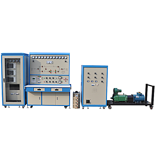
ZOPDLJB-05 Power System Comprehensive Automation Skills Training Device
Power system comprehensive automation skills training device, power training system microcomputer installation human machine interaction interface adopts large -capacity, high -clear 7 -inch color touch screen, which can display the voltage, current, frequency, non -meritoriousness and other electrical parameters of the system in real time. Full touch screen parameter settings and instruction operations.
The platform consists of five parts: synchronous generator set, unit control cabinet, transmission line and monitoring protection screen, infinite power system and impedance load. Operate, test and experiment with teaching content such as automatic devices commonly used in power plants, power plant monitoring, power system operation, relay protection, etc. The device adopts a fixed structure. This tr*ning platform is suitable for practical tr*ning and experiments in courses related to power, electrical , and automation majors in universities, technical secondary schools, and technical schools . It can also be used in the power industry to tr*n personnel engaged in power generation.
2. Characteristics
1. Multi-functional integrated comprehensive experimental device, fully demonstrating the entire process of modern electric energy generation, grid connection and transmission.
2. M*n equipment of the experimental platform: experimental bench , control cabinet, generator set, three-phase adjustable load, etc.
3. The control cabinet includes three parts: microcomputer quasi-synchronous device, microcomputer excitation device, and microcomputer speed regulating device.
4. Complete power experiment content can be carried out: starting and running of the generator set, excitation control of the synchronous generator, quasi-synchronous parallel operation of the synchronous generator, system stability experiment, single machine with load experiment, system grid connection experiment, etc. Up to two More than a dozen types of experiments.
5. The human-computer interaction interface of the microcomputer device adopts a large-capacity, high-definition 7-inch color touch screen, which can display the voltage, current, frequency, reactive power and other electrical parameters of the system in real time. The full touch screen parameter setting and command operation are human-machine friendly. Interactive, the menu can be displayed in Chinese, with pictures and texts.
6. The microcomputer device adopts DSP+CPLD high-end chips: In order to meet the needs of the experimental platform control system, a high-performance, high-precision industrial control 32-bit fixed-point DSP controller is used to realize data processing with software. The function is more powerful, the algorithm is more flexible, and it can It meets the requirements of large amount of calculation and high computing speed; CPLD is a complex programmable logic device that uses computer-*ded design technology to configure the data files generated by the design into the static data memory (SPAM) inside the chip to complete the process. It has repeatable programming It is flexible and can flexibly configure hardware logic circuits, reducing the space and complexity of the PCB board and improving operational reliability. DSP+CPLD is combined and applied to the experimental platform control, and the improved control algorithm and hardware structure are used to make the entire control system meet the requirements of speed, accuracy and stability.
7. Artificial intelligence and adaptive PID control: In order to achieve accurate, smooth and safe adjustment of the generator speed and output voltage, and eliminate oscillation during the control process, this device combines and utilizes conventional PID controllers with self-correction algorithms. The artificial intelligence system automatically adjusts the PID parameters every time the system status changes, so that the control process is always in the optimal state.
8. Modular plug-in controller: The core controller adopts a modular plug-in design. The m*n control unit, AD, DA, digital IO, display and other units are modularized independently of each other. Each module is connected through a bus to ensure the control system reliability, flexibility and m*nt*nability.
9. Has perfect personal protection function
10. Virtual simulation software (copyright certificate and demonstration provided when bidding): This software is in apk format and can be used on PC or mobile. This software can set faults manually or automatically. This software Select the green box in the circuit diagram to manually set the fault point (up to 39 fault points can be set), or the system can automatically set one random fault point, two random fault points, three random fault points, and four random fault points automatically. Settings for each fault point and five random fault points. This software has functions such as toolbox, component library, magnifying glass, circuit diagram, etc. You can select a multimeter for detection through the toolbox, select appropriate components through the component library, and use the magnifying glass to clearly understand Understand each component and circuit. This software allows students to understand the working principle and circuit structure of the motor star-delta start control circuit through the setting of faults in the motor star-delta start control circuit and various investigations.
11. Virtual spectrum analyzer, logic analyzer, oscilloscope, and three-meter simulation software (provide copyright certificate and demonstration when bidding):
This software is in apk format and can be used on PC or mobile terminals. The functions of this software are: resistance measurement, AC voltage measurement (measuring transformer, if the multimeter burns out when measuring the transformer, black smoke will emit prompts and can reset the multimeter), determine the polarity of the transistor, measure the DC voltage (the light turns on when the ammeter is turned on), measure the DC current, and determine the quality of the capacitor. This software can drag the red and black pen tips at will. When the two pen tips are dragged and positioned on the object to be measured, a red circle will be displayed. If the positioning is not accurate, no red circle will be displayed, and when incorrect operations are performed (such as the wrong range selected, If the measured data is wrong, etc.), the meter pointer will be unresponsive, prompting errors and re-measurement, etc. This multimeter can select AC voltage range, DC voltage range, resistance range, current range, resistance adjustment to 0, and can enlarge the display data. Clearly view the measured data size. Students can learn the correct use of multimeters through this software.
Virtual multimeter parameters:
AC voltage ranges: 10, 50, 250, 1000
DC voltage range points: 0.25, 1, 2.5, 10, 50, 250, 1000
Ohm scale: x1, x10, 100, 1000, 1K, x10K, x100K
Ammeter gears: 50μa, 0.5, 5, 50, 500
BATT: 1.2-3.6V, RL=12Ω
BUZZ:R×3
Infrared emission detection function: vertical angle ±15°, distance 1-30cm
Transistor measuring hole
12. Electricity safety and electric shock first *d virtual simulation system (provide copyright certificate and demonstration when bidding)
The software uses a combination of two-dimensional and three-dimensional virtual images to teach students the safety and first *d methods of using electricity. The software includes single-phase electric shock, two-phase electric shock, step electric shock, low-voltage electric shock first *d, high-voltage electric shock first *d, artificial respiration first *d, Principles of hand-holding breathing rescue method, chest cardiac compression and other protective methods are expl*ned and taught. Principles of single-phase electric shock are divided into rep*ring live disconnection, rep*ring socket electric shock, and outdoor electric shock. The teaching of low-voltage electric shock and high-voltage electric shock m*nly expl*ns and demonstrates to students how to rescue people who are suffering from low-voltage electric shock or high-voltage electric shock. Artificial respiration rescue method, hand-holding breathing rescue method, and chest cardiac compression rescue method are demonstrated using 3D virtual simulation technology. After rendering and Polish it to make the model look like the real part and look realistic. Through practical tr*ning, students can be educated on the safe use of electricity in the tr*ning room, improve students' safety awareness, and enable students to learn some self-rescue methods, so that students can take cert*n safety measures to protect themselves when encountering danger, and become familiar with various Causes of electrical accidents and practical measures to deal with them to reduce the occurrence of electrical accidents.
3. Practical tr*ning projects
1. Starting and running of prime mover
2. Speed regulating device operation
3. Speed regulating device and prime mover control
4. Generator electromechanical characteristics
5. Generator no-load characteristic curve test
6. Generator short circuit characteristic curve test
7. Generator external characteristics and adjustment characteristics
8. Generator zero power factor load characteristics
9. Synchronous generator excitation control
10. Basic operation of microcomputer excitation device
11. Observation of excitation voltage waveforms at different α angles (control angles)
12. Synchronous generator starting
13. Control methods and their mutual switching
14. Inverter demagnetization and jump demagnetization switch demagnetization
15. Volkh limit
16. Under-excitation restrictions
17. Synchronous generator forced excitation
18. Adjustment characteristics
19. Overexcitation limit
20. Quasi-synchronous parallel operation
21. Basic operation of microcomputer quasi-synchronous device
22. Automatic quasi-synchronous condition test
23. Linear step voltage formation (phase sensitive link) test
24. Lead time setting and measurement method
25. Pressure difference, frequency difference and phase difference locking and setting
26. Manual quasi-synchronous grid connection
27. Semi-automatic quasi-synchronous grid connection
28. Automatic quasi-synchronous grid connection
29. Stand-alone-infinite system stable operation mode
30. Single loop steady-state symmetrical operation
31. Comparison of steady-state symmetrical operation of double loop and single loop
32. Single-loop steady-state non-full-phase operation
33. Single machine with load
34. Independent system characteristics
35. Throwing and cutting different loads
36. Single machine load shedding
37. Power system power characteristics (power angle) and power limit (static stability)
38. Determination of power characteristics and power limit without regulated excitation
39. Determination of power characteristics and power limits when manually adjusting excitation
40. Determination of power characteristics and power limit when microcomputer is self-shunt excited
41. Determination of power characteristics and power limit when microcomputer is separately excited
42. Relationship between single-circuit and double-circuit transmission power and power angle
43. Improve the static stability of the power system
44. Transient stability of power system
45. Effect of short circuit type on transient stability of power system
46. Effect of fault removal time on transient stability
47. Test on the influence of strong excitation on transient stability
48. Line reclosing and its impact on system transient stability
49. Asynchronous operation and resynchronization of synchronous generators
50. Measures to improve the transient stability of power systems
4. Configuration list
|
serial number |
name |
Specifications and models |
unit |
quantity |
|
1. |
Three-phase synchronous generator |
STC-3/3KW rated excitation voltage 70V, excitation current 3A, speed 1500RPM, voltage 400V |
tower |
1 |
|
2. |
Z4 type DC motor |
Z4-112/2-2 4kw 1500rpm Armature 440V Excitation 180V |
tower |
1 |
|
3. |
Three-phase auto-voltage regulator |
15KVA |
tower |
1 |
|
4. |
Simulate transmission lines and short circuit reactance |
63mh 5A, 127mh 5A |
Only |
12 |
|
5. |
Current Transformer |
CHF-5P, CHF-15P |
Only |
3 |
|
6. |
voltage transformer |
CHV-25P/600, CHV-25P/400, CHV-25P/200 |
Only |
3 |
|
7. |
Electrical instrument |
Voltage, current, frequency, synchronization, etc. |
Only |
twenty two |
|
8. |
AC contactor |
CJX1210 |
Only |
9 |
|
9. |
AC, DC relay |
Only |
25 |
|
|
10. |
transfer switch |
LW8-D |
Only |
8 |
|
11. |
Various buttons |
Inching, self-locking |
Only |
14 |
|
12. |
infinite system |
With isolation transformer |
tower |
1 |
|
13. |
Microcomputer speed regulator |
Touch type, with signal observation point |
tower |
1 |
|
14. |
Microcomputer excitation device |
Touch type, with signal observation point |
tower |
1 |
|
15. |
Microcomputer quasi-synchronous device |
Touch type, with signal observation point |
tower |
1 |
|
16. |
Speed regulating and excitation synchronous transformer |
380V/400V 3kva, 80V/150V 600va, 380V/60V 1kva |
tower |
3 |
|
17. |
Trigger control module |
CF6B-1A |
tower |
3 |
|
18. |
Microcomputer protection device |
RE-8000 |
set |
1 |
|
19. |
Generator and transformer group control panel |
middle man |
tower |
1 |
|
20. |
Power plant system switching control panel |
tower |
1 |
|
|
twenty one. |
Load cabinet (cont*ns inductive and resistive loads) |
tower |
1 |
|
|
twenty two. |
Practical tr*ning guide |
Book |
1 |
- Previous:ZOPDT-188A Electric Technology Experimental Device
- Next:ZOPDLJB-06 Electric Power System Relay Protection Working Device