- Excavator steering system anatomy training desk
- Hydraulic front hanging mechanical experimental device
- Water pump performance experimental device
- Contact oxidation pool training desk
- Drinking water treatment process training desk
- Reverse osmosis membrane training
- Softness and salt removal experimental device
- Salvation tank experimental device
- Aerobic biological treatment training device
- Bio -turntable principle experimental device
- Lucky ratio blocking test device
- Socci condiment training desk
- Industrial wastewater treatment training desk
- Industrial wastewater treatment process simulation experimental device
- CNC milling machine installation and maintenance training table
- CNC Machining Center Maintenance and Processing Technical Experimental Desk
- AC Voltage Merragatory System Electrical Experiment Device
- Solar power generation experimental device
- Electrical experimental device of ship anchor machine
- Worker Electrical Engineering Technology Training Device
WeChat:15372285263
Phone:15372285263
WhatsApp:15372285263
Address:Building 3, No. 7 Longyuan Road, Shuige Industrial Park, Liandu District, Lishui City, Zhejiang Province
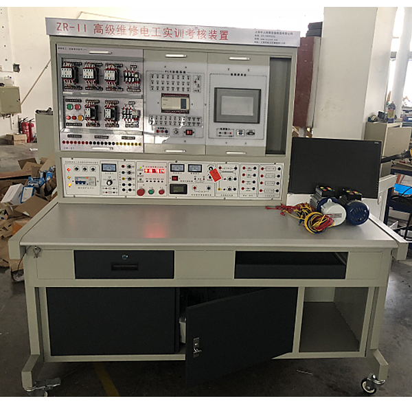
ZOPWXG-01X Advanced Maintenance Electric Training Device
The PLC programmable controller and frequency conversion speed regulator and corresponding training modules equipped with high -level maintenance electrical training descriptions, and quickly master the actual application techniques and operating skills required by the curriculum requirements.
The senior m*ntenance electrician and skills tr*ning assessment tr*ning device is designed according to the requirements of the "Worker Level Standards" and "Occupational Skill Appr*sal" issued by the Ministry of Labor and Social Security. It is applicable to "Elementary M*ntenance Electrician ", "Intermediate "M*ntenance Electrician" and "Advanced M*ntenance Electrician" textbooks require electrical control circuits. Through the tr*ning of the PLC programmable controller and variable frequency speed regulator equipped with the device and the corresponding tr*ning modules, you can quickly master the practical application technology and operating skills required by the course. It is targeted, practical, scientific and advanced. It can meet the requirements of the assessment syllabus for intermediate and advanced m*ntenance electricians. It is an ideal choice for the assessment of the skills of intermediate and advanced m*ntenance electricians by various labor vocational skill appr*sal departments, colleges and universities, and technical schools. equipment.
2. Features of the device:
1. The electrical control circuit components are all installed on the mounting plate as a hanging board, which is easy to operate and replace, making it easy to expand functions or develop new tr*ning, and the selection of operation content is typical and practical;
2 .The operation console only needs three-phase four-wire AC power supply before it can be put into use;
3. The control circuit for skill tr*ning and the specially designed small motor can simulate various electrical drive systems in the factory and satisfy the needs of m*ntenance electricians. Technical requirements for installation, debugging, fault analysis and troubleshooting;
4. The device is equipped with voltage and current leakage protectors to ensure the safety of the operator;
5. All components are led to the terminal blocks through wires, and students When wiring, you only need to wire on the terminals, which is beneficial to protecting components;
6. Route wires through wire troughs for process wiring tr*ning.
7. It has a timing and alarm recorder to provide a unified standard for the assessment of students' practical tr*ning skills.
3. Technical performance:
1. Input voltage: three-phase four-wire (or three-phase five-wire) ~ 380V ± 10% 50Hz
2. Working environment: temperature -10 ~ +40℃, relative humidity <85% (25℃) altitude <4000m
3. Device capacity: <1.5KVA
4. Weight: 120Kg
5. Dimensions: 1600×700×1600mm
6. Leakage protection action current: ≤30mA; leakage protection action time: ≤0.1s.
7. Virtual multimeter parameters:
AC voltage range points: 10, 50, 250, 1000
DC voltage range points: 0.25, 1, 2.5, 10, 50, 250, 1000
ohm range points: x1, x10,,100 ,,1000,,1K,x10K,x100K
ammeter gears: 50μa, 0.5, 5, 50, 500
BATT: 1.2-3.6V, RL=12Ω
BUZZ: R×3
infrared emission detection function: vertical angle ±15° distance 1 -30cm, transistor measuring hole
4. Basic configuration and functions of the device
(1) DW02 power control box
The m*n control screen is an iron double-layer matt dense pattern spray-coated structure.
(2) The m*n control function board is equipped with resources
1. Three-phase four-wire power input, after passing through the leakage protector, passes through the m*n switch, and controls the on and off of the contactor through the start and stop buttons, and is equipped with an emergency stop control button;
2. Control There is a 450V pointer AC voltmeter on the screen, and the three-phase grid voltage can be observed by switching the band switch;
3. Timer and alarm recorder (service manager), usually used as a clock, with set time, scheduled alarm, Functions such as cutting off the power supply; it can also automatically record the total number of leakage alarms and power short circuits caused by wiring or operation errors, providing a unified standard for the assessment of students' practical tr*ning skills;
4. Intelligent multi-functional AC circuit measuring meter: Eight-digit LED display can simultaneously measure the current I, voltage V, power KW, electric energy KWh, and working time T in the working circuit. Accuracy is level 1.0.
5. AC low-voltage power supply: equipped with a transformer, AC voltage of 220V on the primary side, 26V on the secondary side and 6.3V on the secondary side. 6.3V is used for the signal indicator light power supply, and 26V is used for the AC power supply of the rectifier circuit in energy-consuming braking;
6 . There are four 5408 diodes for the rectifier circuit of energy-consuming braking;
7. Three 75Ω/75W resistors are used for motor step-down starting, and one 10Ω/25W is used for energy-consuming braking of asynchronous motors.
8. M*ntenance of electrical and electronic motors and vocational qualification tr*ning assessment simulation software.
This software is in apk format and can be used on PC or mobile. This software can set faults manually or automatically. This software uses circuit diagrams The middle green box selects manual setting of fault points (up to 39 fault points can be set), or the system can automatically set one random fault point, two random fault points, three random fault points, and four random faults. Point setting, five random fault points are set. The software has toolbox, component library, magnifying glass, circuit diagram and other functions. You can select a multimeter for detection through the toolbox, select appropriate components through the component library, and you can clearly understand through the magnifying glass. Various components and circuits. This software allows students to understand the working principle and circuit structure of the motor star-delta start control circuit through the setting of faults in the motor star-delta start control circuit and various investigations.
9. Virtual spectrum analyzer, logic analyzer, oscilloscope, and three-meter simulation software
This software is in apk format and can be used on PC or mobile terminals. The functions of this software are: resistance measurement, AC voltage measurement (measuring transformer, if the multimeter burns out when measuring the transformer, black smoke will emit prompts and can reset the multimeter), determine the polarity of the transistor, measure the DC voltage (the light turns on when the ammeter is turned on), measure the DC current, and determine the quality of the capacitor. This software can drag the red and black pen tips at will. When the two pen tips are dragged and positioned on the object to be measured, a red circle will be displayed. If the positioning is not accurate, no red circle will be displayed, and when incorrect operations are performed (such as the wrong range selected, If the measured data is wrong, etc.), the meter pointer will be unresponsive, prompting errors and re-measurement, etc. This multimeter can select AC voltage range, DC voltage range, resistance range, current range, resistance adjustment to 0, and can enlarge the display data. Clearly view the measured data size. Students can learn the correct use of multimeters through this software.
10. Mechanical tr*ning safety education virtual simulation software.
This software is developed based on unity3d. The software adopts the form of three-dimensional roaming. Movement can be controlled by the keyboard and the lens direction can be controlled by the mouse. It is equipped with mechanical safety distance experiments, mechanical safety protection device experiments, and mechanical safety protection. Design basic assessment. When the experiment is in progress, the three-dimensional roaming screen uses arrows and footprints to prompt the user to move to the experimental location. The circle around the mechanical object shows the working radius. The experimental process is accompanied by a dialog box reminder of the three-dimensional robot. The content is as follows:
A. The mechanical safety distance experiment includes the safety distance experiment to prevent the upper and lower limbs from touching the danger zone (divided into 2 fence heights and opening sizes). After selecting to enter, GB23821-2009 "Mechanical Safety to Prevent Upper and Lower Limbs from Touching" pops up in front of the camera. "Safe Distance in Danger Zone" requirements, error demonstration: The experimental process is that after the human body enters the working radius of the mechanical object and is injured, the red screen and voice prompts that the human body has received the mechanical injury, and returns to the original position and conducts the next experiment. The final step is the correct approach. .
B. Mechanical safety protection device experiments are divided into safety interlock switches, safety light curt*ns, safety mats, safety laser scanners and other protection device experiments. Optional categories (safety input, safety control, safety output, others), manufacturers, products List (safety interlock switch, safety light curt*n, safety mat, safety laser scanner, safety controller, safety relay, safety guardr*l). There is a blue flashing frame reminder at the installation location. Experimental process: select the safety guardr*l and install it, select the safety interlock switch (or select the safety light curt*n, safety mat, safety laser scanner) and install it, select the safety controller and install it in the electrical control box , select the safety relay and install it in the electrical control box, click the start button on the electrical control box. If you enter a dangerous area, the system will sound an alarm and the mechanical object will stop working. Select the reset button on the electrical control box to stop.
C. The basic assessment of mechanical safety protection design requires the completion of the installation of the mechanical safety system, and the correct installation of safety guardr*ls, safety interlock switches, safety light curt*ns, safety mats, safety laser scanners, safety controllers, safety relays, 24V power supplies, signal lights and Emergency stop button, the assessment is divided into ten assessment points. Some assessment points have 3 options, which are freely chosen by the students. After selecting the final 10 assessment points, submit for confirmation, and the system will automatically obt*n the total score and the score of each assessment point. .
D. The software must be on the same platform as a whole and must not be displayed as separate resources.
E. At the same time, we provide customers with the VR installation package of this software to facilitate users to expand into VR experiments. VR equipment and software installation and debugging are not required.
(3) Tr*ning table
The tr*ning table has a steel-wood structure. The table top is made of fireproof, waterproof, wear-resistant high-density board, with a solid structure and beautiful appearance. Equipped with cabinets for placing pendants and tr*ning items.
(4) PLC tr*ning set
PLC tr*ning set one:
1. Music fount*n simulation control 2. Clicker simulation control 3. Assembly line simulation control 4. Crossroad traffic light simulation control 5. Automatic rolling mill simulation control 6. Sky Tower of Light/TV Tower Radio Wave Simulation Control
PLC Tr*ning Set 2:
1. Automatic feeding and loading/conveyor belt simulation control 2. Multiple liquid mixing device/mixer simulation control 3. Vending machine simulation control 4. Water tower automatic water supply simulation control 5. M*l sorting simulation control
PLC tr*ning set three:
1. Basic input/output experiment 2. Four-story elevator automatic control 3. Intermediate relay
PLC tr*ning set four:
1. Electroplating system simulation control 2. Washing machine automatic control 3. LED seven-segment digital tube display control
5. Practical tr*ning items
1. Three-phase asynchronous motor direct start control circuit
2. Three-phase asynchronous motor inching control circuit
3. Three-phase asynchronous motor self-locking control circuit
4. Three-phase asynchronous motor button connection Lock forward and reverse control circuit
5. Three-phase asynchronous motor contactor interlocking forward and reverse control circuit
6. Three-phase asynchronous motor double interlocking forward and reverse control circuit
7. Three-phase asynchronous motor workbench automatic round-trip control circuit
8. Two Three-phase asynchronous motor sequential start and sequential stop control circuit
9. Two-place control circuit of three-phase asynchronous motor
10. Y-△ control controlled by contactor
11. Y-△ control controlled by time relay
12. Three-phase asynchronous motor One-way start reverse connection braking control circuit
13. Three-phase asynchronous motor without transformer half-wave rectification one-way start energy consumption braking control circuit
14. Three-phase asynchronous motor with transformer full-wave rectification one-way start energy consumption braking control circuit
15 .Three-phase asynchronous motor forward and reverse start energy consumption braking control circuit
16. Single-phase squirrel cage motor capacitor start control circuit
17. Two-speed AC asynchronous motor manual transmission control circuit
18. Two-speed AC asynchronous motor automatic transmission control circuit
19. Y-△ start control circuit with power-off delay and DC energy consumption braking
20. Y-△ start control circuit with DC energy consumption braking and power-on delay
21. Three-phase asynchronous motor double interlocking forward and reverse energy consumption braking control circuit
22. Three-phase asynchronous motor double interlocking forward and reverse start and reverse braking control circuit
23. C620 lathe electrical control circuit
24. Electric hoist Control
25. Y3150 gear hobbing machine control circuit
26. Basic command operation of programmable controller
27. Music fount*n simulation control experiment
28. Clicker simulation control experiment
29. Assembly line simulation control experiment
30. Crossroad traffic light simulation control experiment
31. Automatic rolling mill simulation control experiment
32. Sky Tower Light/TV Tower Radio Wave Simulation Control Experiment
33. Automatic feeding and loading/conveyor belt simulation control experiment
34. Multiple liquid mixing device/mixer simulation control experiment
35. Vending machine simulation control experiment
36. Water tower automatic water supply simulation control experiment
37. M*l sorting simulation control experiment
38. Four-story elevator automatic control experiment
39. Intermediate relay experiment
40. Electroplating system simulation control experiment
41. Washing machine automatic control experiment
42. LED seven-segment digital tube display Control experiment
42. PLC controlled three-phase asynchronous motor forward and reverse control
43. PLC controlled three-phase asynchronous motor Y-△ start control
44. PLC controlled three-phase asynchronous motor step-down start control
45. PLC controlled three-phase asynchronous motor Motor energy consumption braking control
46. Frequency converter function parameter setting and operation
47. Frequency converter alarm and protection functions
48. Multi-stage speed selection and frequency conversion speed regulation
49. External terminal jog control
50. Control of motor forward and reverse motion control
51. Control Motor running time operation
52. Instantaneous power outage inverter parameter setting
53. External voltage frequency conversion speed regulation
54. External current frequency conversion speed regulation
55. Frequency conversion open-loop speed regulation of three-phase asynchronous motor
56. PLC controls the motor positive direction of the external terminal of the frequency converter Reverse rotation
57. PLC controls the motor running time control of the external terminals of the frequency converter
58. Multi-stage speed based on PLC digital control method
59. Open-loop speed regulation of the frequency converter based on PLC communication method
60. Speed closed-loop control based on PLC communication method
61 .Simulation of constant pressure water supply system with frequency converter
62.Basic instruction programming exercise based on touch screen control method
63..LED control based on touch screen control method
64..PLC, touch screen and frequency converter communication control
6. Tr*ning component configuration
|
serial number |
Practical tr*ning module name |
quantity |
Remark |
|
1 |
M*ntenance electrician practical tr*ning and assessment components (1) |
1 item |
Thermal relay, AC contactor 380V, button, indicator light (6.3V), terminal blocks, etc. |
|
2 |
M*ntenance electrician practical tr*ning and assessment components (2) |
1 item |
Screw-type fuses, push-in fuses, low-voltage circuit breakers, time relays, AC contactors, terminal blocks, etc. |
|
3 |
M*ntenance electrician practical tr*ning and assessment components (3) |
1 item |
Screw-type fuses, transfer switches, solenoid valves, cross switches, travel switches, etc. |
|
4 |
M*ntenance electrician practical tr*ning and assessment components (4) |
1 item |
Provides two sets of 90Ω×2/1.3A disk resistors; one set of 900Ω×2/0.41A disk resistors. |
|
5 |
PLC programmable controller tr*ning components |
1 item |
Provide Mitsubishi FX1N-40MR-001 host |
|
6 |
PLC tr*ning set |
1 set |
Familiar with the usage of PLC instructions and programming methods |
|
7 |
Frequency converter tr*ning components |
1 item |
Provide Mitsubishi FR-D720S-0.4KW frequency converter, which can conduct communication tr*ning with PLC |
|
8 |
SC-09 programming cable |
1 |
Used for communication between PLC host and PC |
|
9 |
Programming software |
1 set |
Provide Mitsubishi SWOPC-FXGP/WIN-C programming software |
|
10 |
Mesh practical board |
1 piece |
By matching components, students can fix, install, layout, route and debug on the mesh board by themselves, which can cultivate students' hands-on ability and operating skills. The mesh board can also be used as an expansion module for practical tr*ning projects. |
|
11 |
Single phase capacitor starting motor |
1 set |
AC 220V |
|
12 |
Three-phase squirrel cage asynchronous motor |
1 set |
AC 380V, △/Y |
|
13 |
Three-phase squirrel cage asynchronous motor |
1 set |
AC 380V, △/Y (with speed relay) |
|
14 |
Three-phase two-speed asynchronous motor |
1 set |
AC 380V, △/Y |
|
16 |
Experimental bench |
1 set |
|
|
17 |
Color touch screen |
1 set |
7 inch |
- Previous:ZOPDG-WS maintenance electrical comprehensive training device
- Next:ZOPWXC-082 Intermediate repair electricity experimental device