WeChat:15372285263
手机:15372285263
WhatsApp:15372285263
地址:浙江省丽水市莲都区水阁工业园绿源路7号3栋
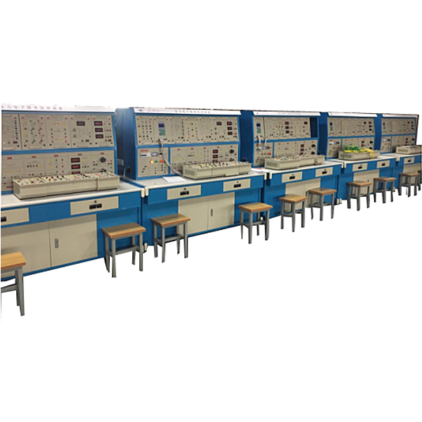
ZOPDDZ-03 Power Electronics Technology Experimental Device
The power electronics technology experimental training device and the power electronics experimental bench experimental pendant adopt a partitioned structure, with the experimental schematic diagram and test points on the front, which enhances students‘ perceptual and rational understanding of the experimental content; the panel layout is reasonable, the patch cord is convenient, and students can operate the experiment independently.
I. Overview
The "Power Electronics Technology Experiment and Tr*ning Device" is a skill tr*ning device developed to meet the requirements of the experimental tr*ning syllabus for courses such as "Power Electronics Technology", "Semiconductor Converter Technology", and "AC/DC Speed Regulation" offered by colleges and universities. It can also be used as a skill tr*ning device for junior and intermediate m*ntenance electricians , senior electricians, technicians, and senior technicians.
2. Technical Features
1. Safe and reliable: This device is powered by an isolation transformer and has grounding protection and leakage protection functions. Its safety complies with relevant national standards to ensure personal safety. According to the characteristics of different experimental projects, it is equipped with two different experimental connection lines. The strong current part adopts a high-reliability sheath structure pistol plug connection line (there is no possibility of electric shock), and the weak current part adopts an elastic beryllium light copper exposed structure connection line. Both wires can only be used with sockets with corresponding inner holes, which greatly improves the safety and rationality of the experiment.
2. Strong scalability: It can meet the experimental teaching of corresponding courses in various schools. The depth and breadth of the experiment can be flexibly adjusted according to needs, and popularization and improvement can be organically combined according to the progress of teaching. The device adopts a pendant structure, which is easy to replace. If you need to expand functions or develop new experiments, you only need to add components, and it will never be eliminated.
3. Strong intuitiveness: The experimental pendant adopts a separated structure, with the experimental principle diagram and test points on the front, which enhances students' perceptual and rational understanding of the experimental content; the panel layout is reasonable, the connection lines are convenient, and students can operate the experiment independently, which is conducive to improving students' practical hands-on ability.
4. Strong advancement: The experiments involve four commonly used types of power conversion technology experiments, and most of them are practical circuits that are widely used, but for the convenience of teaching, they do not lose their simplicity; this device also considers the new devices from a high level, adding new device characteristic experiments, new device driving and typical new device application modern power electronics technology experiments, so that students can have sufficient knowledge and understanding of new devices and keep up with the pace of the times.
3. Technical performance
1. Input voltage: three-phase four-wire ~ 380V ± 10% 50Hz
2. Working environment: ambient temperature -10℃~+40℃ relative humidity <85% (25℃) altitude <4000m
3. Device capacity: <1.5kVA
4. Device size: 1600mm×700mm×1570mm (about 5%)
4. Basic equipment of the tr*ning device
The tr*ning device consists of a control panel, a tr*ning table and various tr*ning components.
1. Control panel: It adopts a frame structure, which is compact, firm, and beautiful. Tr*ning components can be hung on the upper layer of the control panel.
(II) Practical tr*ning components:
1. PE-01 AC power supply assembly
Provides three-phase adjustable AC power supply (range single-phase: 0-250V; three-phase 0-450V), with built-in overcurrent protection and leakage protection functions, and is equipped with isolation transformer output, which ensures safe tr*ning.
(1) The three-phase power supply first passes through the three-phase leakage protector, and then through the contactor to the isolation transformer to isolate the output from the power grid (floating ground design).
(2) Current type leakage protection device: If there is leakage in the control panel and the leakage current exceeds a cert*n value, the power supply will be cut off.
2. PE-02 power diode assembly
Provide seven high-power rectifier diodes (fuse protection circuit) and one button switch for rectification and freewheeling.
3. PE-03 thyristor assembly
Provides 6 unidirectional thyristors for controlled rectification tr*ning, equipped with RC resistance-capacitance absorption and fuse protection circuit.
4. PE-04 Bidirectional Thyristor Component
Provide 3 bidirectional thyristors for AC voltage regulation circuit tr*ning
5. PE-05GTR, MOSFET, IGBT components
Provide three power devices: GTR (high power transistor), MOSFET (power field effect transistor), IGBT (insulated bipolar transistor)
6. PE-06 three-phase core transformer assembly
Provide a 63.5V, 0.8A/127V, 0.4A core transformer
7. PE-07 three-phase synchronous transformer assembly
It is composed of three synchronous transformers and a three-pole three-throw switch.
8. PE-07D lamp load assembly
It is composed of three 250V/4A lamp holders and is used as a resistive load during tr*ning.
9. PE-08 Reactor and Transformer Components
Provide a set of smoothing reactors, av*lable in 100mH, 200mH, 700mH, and a dual-circuit 220V transformer
10. PE-9 setting and voltage indication components
Provides continuously adjustable +15V and -15V given voltages with output indication.
11. PE-10 AC parameter table assembly
Provide an AC digital voltmeter with a measurement range of 0-500V, a precision of 0.5, a three-and-a-half-digit display, and an input impedance of 10MΩ
Provide two AC digital ammeters with a measuring range of 0 to 5A, a precision of 0.5, and a three-and-a-half-digit display.
12. PE-11 DC current parameter meter component
Provide a DC digital voltmeter with a measurement range of 0-300V, a precision of 0.5, a three-and-a-half-digit display, and an input impedance of 10MΩ
Two DC digital ammeters are provided, with a measuring range of 0 to 5A, a precision of 0.5 level, and a three-and-a-half-digit display.
13. PE-12 single-phase thyristor trigger circuit
A unijunction transistor is provided to generate a trigger signal for controlling a rectifier circuit composed of a single-phase thyristor;
14. PE-12BTCA785 integrated trigger circuit
Siemens TCA785 is provided . Compared with KC04 (KC09), it has more reliable zero point recognition, better output pulse uniformity, and a wider phase shift range. At the same time, its output pulse can be freely adjusted manually, and can be used for single-phase rectification or voltage regulation circuit tr*ning.
15. PE-13TC787 Trigger Circuit Assembly
The TC787 chip is used to form a three-phase fully controlled trigger circuit, which has the advantages of stable and reliable output, high input impedance, good anti-interference performance, etc. It is also easy to install and adjust and reliable to use. Only one such integrated circuit is needed to complete the three-phase phase shift function.
16. PE-14 adjustable resistor assembly
Provides one 90Ω×2/1.3A adjustable resistor and one 900Ω×2/0.41A adjustable resistor, used as pure resistive load
17. Teaching software
1. Electrical safety and electric shock first *d simulation teaching software
The software uses a combination of two-dimensional and three-dimensional virtual images to teach students the safety and first *d methods of electricity use. The software has single-phase electric shock, two-phase electric shock, step electric shock, low-voltage electric shock first *d, high-voltage electric shock first *d, artificial respiration rescue method, hand-holding breathing rescue method, chest cardiac compression rescue method and other principle explanations and teaching. Single-phase electric shock is divided into m*ntenance of live disconnection, m*ntenance of socket electric shock, outdoor electric shock and other principle demonstrations. Low-voltage electric shock and high-voltage electric shock teaching m*nly expl*n and demonstrate to students how to rescue people in low-voltage electric shock or high-voltage electric shock. Artificial respiration rescue method, hand-holding breathing rescue method, chest cardiac compression rescue method are displayed using 3D virtual simulation technology. After rendering and polishing, the model looks the same as the real part and the picture is realistic. Through practical tr*ning, students can be educated on safe use of electricity in the tr*ning room, improve their safety awareness, learn some self-rescue methods, and take cert*n safety measures to protect themselves when they encounter danger, as well as be familiar with the causes of various electrical accidents and practical operational measures for handling electrical accidents, so as to reduce the occurrence of electrical accidents.
2. M*ntenance of electrical and electronic machinery and professional qualification tr*ning and assessment simulation software
This software is in apk format and can be used on PC or mobile. This software can set faults manually or automatically. This software can select the manual setting of fault points through the green box in the circuit diagram (up to 39 fault points can be set), or the system can automatically set one fault point at random, two fault points at random, three fault points at random, four fault points at random, and five fault points at random. This software has toolbox, component library, magnifying glass, circuit diagram and other functions. You can select a multimeter for detection through the toolbox, select appropriate components through the component library, and use a magnifying glass to clearly understand each component and circuit. This software sets the fault of the motor star-delta starting control circuit and, after various investigations, allows students to understand the working principle and circuit structure of the motor star-delta starting control circuit.
3. Virtual spectrum analyzer, logic analyzer, oscilloscope, three-meter simulation software:
This software is in apk format and can be used on PC or mobile. The functions of this software include: resistance measurement, AC voltage measurement (measuring transformers, if the transformer burns out the multimeter, black smoke will be emitted and the multimeter can be reset), transistor polarity judgment, DC voltage measurement (the light is on when the ammeter is turned on), DC current measurement, and judgment of the quality of capacitors. This software can drag the red and black pen heads at will. When the two pen heads are dragged to the measured object for positioning, a red circle will be displayed. If the positioning is not accurate, no red circle will be displayed. When an incorrect operation is performed (such as the selected range is wrong, the measured data is wrong, etc.), the instrument pointer will not respond, prompting an error to re-measure, etc. This multimeter can select AC voltage, DC voltage, resistance, current, resistance adjustment 0, and can enlarge the displayed data, so that the size of the measured data can be clearly viewed. Students can learn the correct use of multimeters through this software.
4. Single chip microcomputer , PLC programmable design and control virtual simulation software:
This software is developed based on unity3d, and has built-in experimental steps, experimental instructions, circuit diagrams, component lists, connection lines, power on, circuit diagrams, scene reset, return and other buttons. After the connection and code are correct, the 3D machine tool model can be operated through the start/stop, forward motion, and reverse motion buttons. When the line is connected, the 3D machine tool model can be enlarged/reduced and translated.
1. Relay control: Read the experiment instruction manual and enter the experiment. By reading the circuit diagram, select relays, thermal relays, switches and other components in the component list and drag them to the electrical cabinet. Place the limiter on the 3D machine model. You can choose to cover the lid. Some component names can be renamed. Then click the connect line button to connect the terminals. After the machine tool circuit is successfully connected, choose to turn on the power and operate. If the component or line connection is wrong, an error box will pop up and the scene can be reset at any time.
2.PLC control: The experiment is the same as the relay control, with the addition of the PLC control function. After the connection is completed, press the PLC coding button to enter the program writing interface, write two programs, forward and reverse, with a total of 12 ladder diagram symbols. After writing, select Submit for program verification. After successful verification, turn on the power to operate. Error boxes will pop up for components, line connections, and code errors, and the scene can be reset at any time.
3. Single-chip microcomputer control: The experiment is the same as relay control, with the addition of single-chip microcomputer control function. After the connection is completed, enter the programming interface through the C coding button, enter the correct C language code, submit and verify successfully, turn on the power to operate, and a prompt error box will pop up for component, line connection, and code errors, and the scene can be reset at any time.
5. Tr*ning Project
1. Tr*ning on characteristics of power devices and auxiliary components
(1) Power diode characteristic test
(2) Thyristor SCR characteristic test
(3) Bidirectional thyristor BCR characteristic test
(4) IGBT characteristics test
(5) MOSFET characteristics test
(6) GTR characteristic test
2. Trigger circuit tr*ning
(1) Unijunction transistor trigger circuit (BT35/BT33)
(2) Siemens TCA785 single-phase integrated trigger circuit
(3) TCA787 three-phase integrated trigger circuit
3. AC-DC rectifier circuit tr*ning
Uncontrolled Rectification
(1) Single-phase half-wave uncontrolled rectifier circuit
(2) Single-phase full-wave bridge uncontrolled rectifier
(3) Transformer center-tapped double half-wave uncontrolled rectification
(4) Three-phase star-connected uncontrolled rectifier circuit
(5) Three-phase bridge full-wave uncontrolled rectifier
Controlled Rectification
(1) Single-phase half-wave controlled rectifier
(2) Single-phase bridge half-controlled rectification
(3) Single-phase bridge fully controlled rectifier
(4) Transformer center-tapped double half-wave controlled rectification
(5) Three-phase star connection half-wave controlled rectification
(6) Three-phase bridge half-controlled rectifier circuit
(7) Three-phase bridge fully controlled rectifier
4.DC-AC inverter circuit tr*ning
(1) Single-phase bridge rectifier active inverter
(2) Three-phase bridge rectifier active inverter
5. AC-AC voltage regulation circuit tr*ning
(1) Single-phase thyristor AC voltage regulation circuit
(2) Three-phase thyristor AC voltage regulation circuit
(3) Single-phase bidirectional thyristor AC voltage regulation circuit
(4) Three-phase bidirectional thyristor AC voltage regulation circuit
7. Equipment Configuration List
Serial number | serial number | name | quantity |
1 | PE-01 | AC power supply components | 1 item |
2 | PE-02 | Power diode components | 1 piece |
3 | PE-03 | Thyristor components | 1 item |
4 | PE-04 | Bidirectional thyristor components | 1 item |
5 | PE-05 | GTR, MOSFET, IGBT components | 1 item |
6 | PE-06 | Three-phase core transformer assembly | 1 item |
7 | PE-07 | Synchronous transformer components | 1 item |
8 | PE-07D | Lighting group load components | 1 item |
9 | PE-08 | Reactor and transformer components | 1 item |
10 | PE-9 | Given and voltage indication components | 1 item |
11 | PE-10 | AC Parameter Table Components | 1 item |
12 | PE-11 | DC parameter meter components | 1 item |
13 | PE-12 | Single crystal thyristor trigger circuit | 1 item |
14 | PE-12B | TC785 trigger circuit | 1 item |
15 | PE-13 | TC787 trigger circuit components | 1 item |
16 | PE-14 | Adjustable resistor components | 1 item |
17 | Laboratory table | Iron rectangular closed structure, beautiful and elegant shape; equipped with drawers and doors for placing tools, hanging accessories and documents | 1 set |
18 | Test bench | Provide power supply and supporting system operation units | 1 set |
19 | Experimental connection line | Equipped with two different tr*ning connection cables, the two cannot be plugged into each other, ensuring safe tr*ning. | 1 set |
20 | Guiding book | Provide hardcover experimental guide | 1 set |
Hot-selling products: Electrician tr*ning table
- 上一篇:ZOPDDL-2 Circuit Analysis and Power Electronics Technology Experimental Device
- 下一篇:Dispositivo experimental de tecnología electrónica de potencia ZOPDDZ-03